background image

5

POWE

R

12V


--A MA

X

IN

PUT

S

OUT

PUT

S

1

TP

HDM

I

L

R

AUD

IO

HDM

I/C

EC

SIG

LIN

K

COM

IR

DIG

ITA

L I/O

1

2

S

G

Tx

Rx

G

G

3

4

G

HCR

 10

2

LAN

IN

Installation and Configuration

ATTENTION:


• 

Installation and service must be performed by experienced personnel.

• 

L’installation et l’entretien doivent être effectués par du personnel expérimenté.

Step 1 — Get Ready

1. 

Familiarize yourself with the features of the transmitter and receiver (see 

Front and Side Panel Features

 on page 3 and 

Rear, Side, and Front Panel Features

 on the previous page).

2. 

Download and install the latest version of the following:

• 

PCS Product Configuration Software

 — for detecting and configuring the AV settings for the transmitter-receiver pair

• 

Toolbelt software

 — for discovering the HCR 102 receiver and other control products on the network, for managing 

core settings, and for upgrading firmware if the need arises

• 

Global Configurator

®

 (GC) software

 — for setting up and configuring the control system. GC Professional and GC Plus 

modes include a link to the 

Toolbelt

 software.

• 

IP Link

®

 Pro device drivers

 — for use with GC, to make control of other AV devices possible

All are avail able from 

www.extron.com

 (see 

Locating Software, Firmware, and Driver Files on the Extron Website

 on page 18).

3. 

 Obtain network information for the unit from the network administrator. You will need the following details for each HCR 102 
receiver and for any other Extron Pro control product that is part of the system:


…

DHCP setting (on or off)


…

Subnet mask


…

Username


…

Device (HCR 102) LAN IP address


…

Gateway IP address


…

Passwords

4. 

Write down the MAC address of each HCR 102 (see figure 4, 

O

 on the previous page) or other IP Link Pro device to be used.

5. 

Obtain model names and setup information for devices the HCR 102 will control.

Step 2 — Mount the Receiver, Prepare the Installation Site for the Transmitter

Turn off or disconnect all equipment power sources and mount the transmitter and receiver as required 

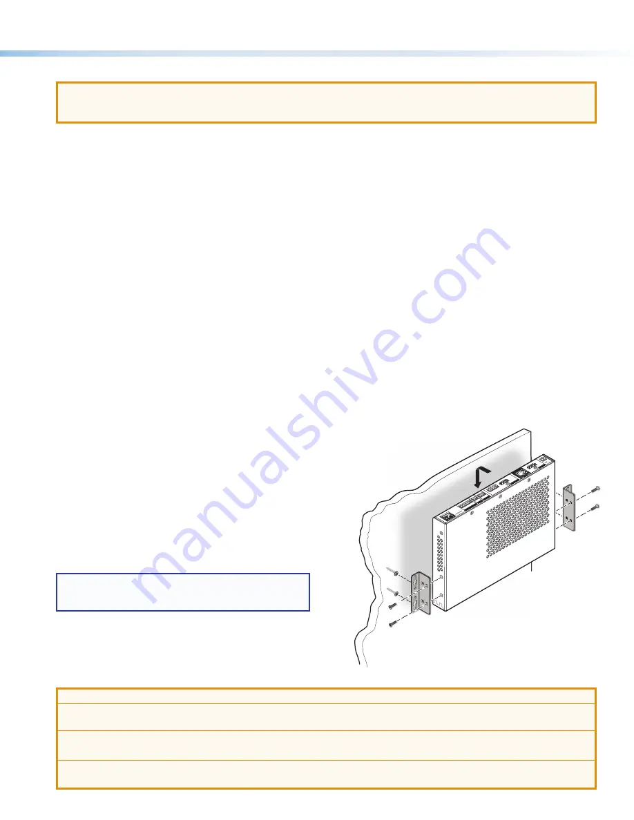
Mounting the HCR 102

The HCR 102 receiver ships with furniture mounting brackets attached 
for mounting to furniture or a wall. The receiver is one inch high, one 
half rack wide, and can be rack mounted. The product page on 

www.extron.com

 includes links to recommended optional rack 

shelves or rack mounting kits. Alternatively, you can remove the 
pre-installed furniture mounting brackets and attach four rubber 
feet at the corners of each unit and place it on a table or desk.
Observe local and UL safety guidelines for mounting devices to 
equipment racks. See the 

HC 400 Series User Guide

 for UL rack 

mounting guidelines.

NOTE:

  The receiver is designed so that its vents face 

away from the wall or furniture when mounted in order 
to achieve optimal air circulation and cooling.

Prepare the Installation Site for the Transmitter

ATTENTION:


• 

Installation and service must be performed by authorized personnel only.

• 

L’installation et l’entretien doivent être effectués uniquement par un technicien qualifié.

• 

Extron recommends installing the HCT 102 EU or HCT 102 MK into a grounded electrical junction box.

• 

Extron recommande d’installer le HCT 102 EU ou HCT 102 MK dans un boîtier d’encastrement électrique mis à la terre.

• 

Follow all national and local building and electrical codes that apply to the installation site.

• 

Respectez tous les codes électriques et du bâtiment, nationaux et locaux, qui s’appliquent au site de l’installation.

1. 

 and of any TouchLink Pro touchpanels or NBP button panel that will be 
part of the system

Figure 5. 

Mounting the Receiver

Содержание HC 403 EU

Страница 1: ...wall boxes The HCT 102 MK transmitter has an MK style faceplate and fits most standard two gang MK type wall boxes The HCR 102 receiver is wall furniture or rack mountable The EU and MK transmitter mo...

Страница 2: ...DIO OUT LAN PoE VGA OUT HDMI OUT USB 3 POWER 5V 2 3A MAX RESET A PoE B POWER 12V 1 7A MAX HDMI HDMI Tx Rx G RS 232 COM L AUDIO R OUTPUT 1 C T 2 C T 3 C T 4 C T G V CONTACT TALLY LAN INPUT OUTPUT TCP I...

Страница 3: ...various product settings to be reset to the factory defaults see Reset Modes a Brief Summary on page 17 I Reset and power LED This green LED indicates either the power status of the transmitter or th...

Страница 4: ...put output control ports page 14 N LAN Ethernet connector and LEDs page 14 O MAC address on side of receiver page 14 P Reset button HCT 102 EU MK If the transmitter powers on but is otherwise unrespon...

Страница 5: ...s of each HCR 102 see figure 4 O on the previous page or other IP Link Pro device to be used 5 Obtain model names and setup information for devices the HCR 102 will control Step 2 Mount the Receiver P...

Страница 6: ...ser or installer must furnish the wall junction box It is not included with the unit Read any installation instructions and safety and regulatory guidelines that come with the wall box before installa...

Страница 7: ...word system and control port settings This requires a PC software and a LAN connection To configure network settings from the OSD menu From the Quick Setup menu DHCP Select and enter the DHCP Mode sub...

Страница 8: ...cted to the network 4 In Toolbelt use the MAC address to locate the desired device the HCR 102 in the list and select it 5 Use the Set IP feature in Toolbelt or use the Toolbelt Manage Network Setting...

Страница 9: ...set the audio input format see table below for the selected input set program audio volume and set audio output format stereo mono Audio Input Format Details None Mutes all audio for selected input Se...

Страница 10: ...ts control ports function What to monitor How to control other products When to do things Which touchpanels to interact with Whom to notify how and under what circumstances a Configure the control por...

Страница 11: ...R HDCP HDMI VG A AU TO VGA IN HCT 102 EU AUDIO IN AUDIO IN Wall Box Mounting Plate Extron HCT 102 EU 3 Secure the transmitter to the mounting plate as follows a Insert the included screws through the...

Страница 12: ...move any excess length Complete details on LockIt installation are available in the LockIt HDMI Cable Lacing Bracket Installation Guide Transmitter Receiver Interconnection Connect the Out port of the...

Страница 13: ...orts must be configured using Global Configurator Serial For serial control using RS 232 connect the serial control port of the AV device to the COM port see figure 3 K on page 4 of the HCR 102 receiv...

Страница 14: ...n 2 LAN XX XX XX E 2 2 XX XX XX X E LAN Insert Twisted Pair Wires Pins 1 2 3 4 5 6 7 8 HCR 102 Rear Panel Ethernet Link LED Activity LED PC AV Device TCP IP Network LAN Ethernet Default protocol IP ad...

Страница 15: ...LAN Tx Rx G RS 232 OVER TP Tx Rx G RS 232 POWER REMOTE 12V A MAX OUT SIG LINK HCT 102 R POWER 12V A MA Ground all devices Return AV and Communication Only 12 VDC input 12 VDC input Ridged Smooth Exte...

Страница 16: ...CM 2Ch and Multi Ch These two LEDs E on the receiver indicate the presence or absence of the specific types of audio signal on the selected active input Audio LED Type Audio Input LED State and Indica...

Страница 17: ...orted on firmware version 1 01 or higher By default DHCP is off and the unit uses a static IP address When you disable the DHCP client by using this mode the unit reverts to using the previously set s...

Страница 18: ...he software file For other software there is a link for contacting an Extron support representative who can provide you access to the latest version To obtain Extron control product software you must...

Отзывы: