


4
HC 403 EU, HC 403 MK • Setup Guide (Continued)
Rear, Side, and Front Panel Features
POWER
12V
2.0A MAX
INPUTS
OUTPUTS
1
TP
HDMI
L
R
AUDIO
HDMI/CEC
SIG
LINK
IN
COM
IR
DIGITAL I/O
1 2
S G
Tx Rx G
G 3 4 G
HCR 102
LAN
MAC: 00-05-A6-
XX-XX-XX
S/N: ####### E######
00-05-A6-XX-XX-XX
A
F
N
D
G
H
K L
M
HCR 102 Rear
O
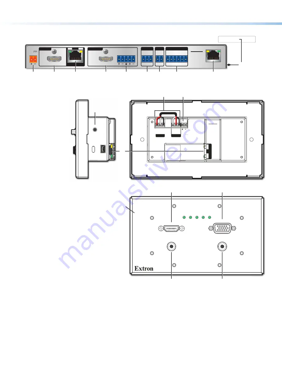
Figure 3.
HCR 102 Rear Panel
A
Power input
connectors, page 15
B
Audio input
connector, page 12
C
Analog RGB video input
, page 12
D
HDMI input
connectors, page 12
E
Transmitter output
RJ-45 connector
(twisted pair interconnection),
page 12
F
Receiver input
RJ-45 connector (twisted
pair interconnection), page 12
G
HDMI/CEC output
connector, page 13
H
Analog audio output
connector, page 13
K
COM RS-232
control port, page 13
L
IR output
control port, page 13
M
Digital I/O
(digital input/output) control ports,
page 14
N
LAN (Ethernet)
connector and LEDs, page 14
O
MAC address
(on side of receiver), page 14
P
Reset button (HCT 102 EU/MK ) — If the transmitter powers on but is otherwise unresponsive or uncommunicative after a
failed firmware upload, you can manually boot up the unit to use the factory firmware code by pressing and holding this
Reset
button while applying power. You must then load new firmware via the HCR 102 receiver (see the
HC 400 Series User
Guide
for instructions).
Q
Over TP and Remote RS-232 connectors (HCT 102 EU/MK ) (factory pre-wired, used for transmitter-receiver inter-unit
communication only)
Figure 4.
HCT 102 MK Side Panel (Top Left), Rear Panel (Top Right),
Front Panel (Bottom)
HDMI IN
PWR HDCP HDMI VGA AUTO
VGA IN
HCT 102 MK
AUDIO IN
AUDIO IN
RESET
SERVICE
Tx Rx G
RS-232
OVER TP
Tx Rx G
RS-232
POWER
REMOTE
12V
A MAX
OU
T
SIG
LIN
K
HCT 102
A
Q
B
B
C
D
HCT 102 MK Front
HCT 102 MK Rear
HCT 102 MK Side
P
Input 3
Input 2
E
Faceplate


