


6
HC 403 EU, HC 403 MK • Setup Guide (Continued)
ATTENTION:
•
If the HCT 102 will be installed into fine furniture, it is best to hire a licensed, bonded craftsperson to cut the access
hole and perform the physical installation so the surface will not be damaged.
•
S’il est prévu d’installer le HCT 102 dans du beau mobilier, il est préférable de faire appel à un artisan autorisé et
qualifié pour couper le trou d’accès et réaliser l’installation de telle façon que la surface ne soit pas endommagée.
Americans with Disabilities Act (ADA) compliance
When planning where to install the HC 400 Series units, you may need to consider factors affecting accessibility of the units
such as height from the floor, distance from obstructions, and how far a user must reach to press buttons or connect a cable. For
guidelines, see sections 307 (“Protruding Objects”) and 308 (“Reach Ranges”) of the
2010 ADA Standards for Accessible Design
available at
http://www.ada.gov/regs2010/2010ADAStandards/2010ADAStandards.pdf
.
Site preparation
The HCT 102 EU fits a standard two-gang European wall (junction) box or external wall box.
The HCT 102 MK fits a standard two-gang MK-type junction box or external wall box.
•
The end user or installer must furnish the wall (junction) box. It is not included with the unit.
•
Read any installation instructions and safety and regulatory guidelines that come with the wall box before installation.
•
Protect the mounting surface to prevent damage.
To prepare the site:
1.
For installation into a wall or furniture:
Measure, mark, and carefully cut a hole in the mounting surface.
For all types of installations:
Run cables
to the
junction box.
2.
Secure the cables with a clamp for strain relief and so they do not slip back down into the wall or furniture.
3.
Secure the box to the raceway, stud, wall, or furniture.
4.
For wall mount installations,
attach the mounting bracket (metal) to the junction box or external wall box.
For raceway installations
, attach the metal mounting bracket to the junction box or external wall box and raceway.
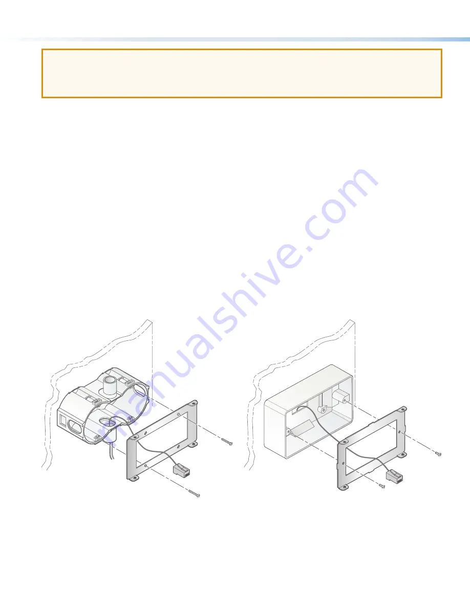
a.
Hold the mounting plate and feed the cables through the mounting plate.
Wall Box
Metal Bracket
External Wall Box
Metal Bracket
Figure 6.
Mounting the Bracket to an EU Wall Box
b.
Place the mounting plate against the box, aligning the holes in the plate with the corresponding threaded holes on the
edges of the box.
c.
Insert the provided screws into those holes, hold the mounting plate to ensure it is aligned straight (visually level), and
tighten the screws to secure the plate to the mounting surface.
Figure 7.
Mounting the Bracket to an MK Wall Box


