1
IMPO
RTAN
T:
Go to www
.extron.com f
or the complete
user guide
, installation instructions,
and
specifications bef
ore connecting the
product to the po
wer sour
ce.
EBP 100 and EBP 200 • Setup Guide
The Extron EBP 100 and EBP 200 eBUS
®
Button Panels are fully customizable AV system control interfaces for use with Extron
IPCP Pro Series Control Processors.
Each EBP button panel includes two eBUS ports, which support both power and communications between the IPCP Pro
control processor and eBUS devices. Up to eight eBUS endpoint devices such as EBP button panels can be connected to
the control processor and to each other in various cabling topologies. Cabling topology refers to the physical layout of cabling
interconnections between devices in a network such as an eBUS system. eBUS systems can include daisy chain, star, or hybrid
system (a combination of both types) topologies (see the
EBP 100 and EBP 200 User Guide
for basic diagrams). Every endpoint
device must have a unique identification address (bus ID) within the system.
Setup involves setting bus ID DIP switches on the EBPs, then using Extron Global Configurator
®
(GC) Plus and Professional
software, or Global Scripter programming, to configure the control processor. Once configured, the AV system can be controlled
from any of its EBPs.
This guide provides basic instructions for an experienced installer to install an EBP 100 or EBP 200 button panel. For more details
on the EBPs, see the
EBP 100 and EBP 200 User Guide
, available on
. For details on configuration, see the
software help files.
Features
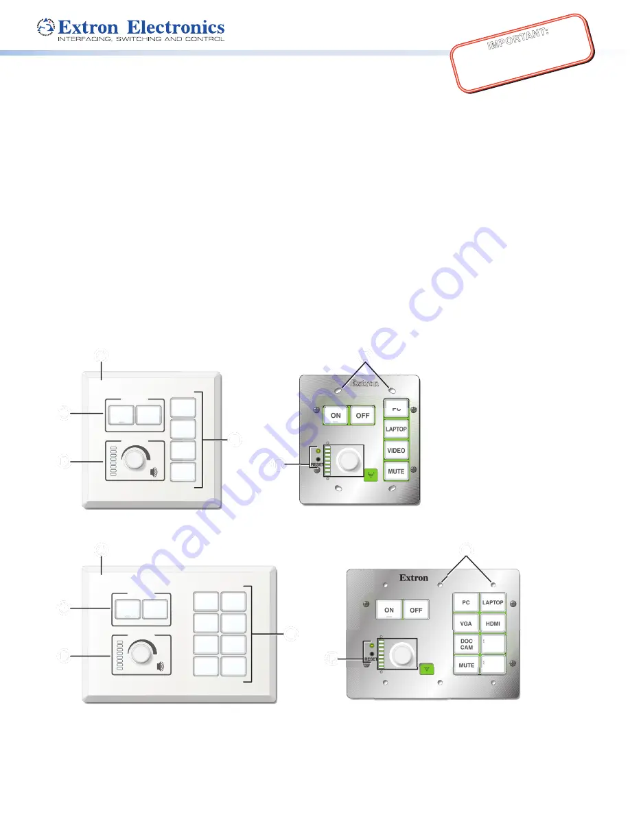
Front Panel Features
Extron
DISPLAY
ON
PC
VIDEO
OFF
LAPTOP
MUTE
VOLUME
Extron
ON
VID
OFF
LAP
MU
VOLUME
PC
E
RESET
E
PC
DOC
CAM
VGA
ON
OFF
MUTE
LAPTOP
HDMI
SCREEN
UP
SCREEN
DOWN
RESET
Extron
DISPLAY
VOLUME
Extron
VOLUME
ON
OFF
PC
DOC
CAM
VGA
MUTE
LAPTOP
HDMI
SCREEN
UP
SCREEN
DOWN
C
C
C
C
D
D
D
D
D
D
D
D
C
C
C
C
B
B
B
B
A
A
A
A
B
B
B
B
A
A
A
A
EBP 100 Front Panel with Faceplate
EBP 100 Front Panel without Faceplate
E
E
E
E
F
F
F
F
F
F
F
F
EBP 200 Front Panel with Faceplate
EBP 200 Front Panel without Faceplate
E
E
E
E
Figure 1.
Front Panels With and Without Faceplates
A
Faceplate
B
Mounting holes
(EBP 100: x4, EBP 200: x6)
C
Display power buttons
D
Volume LEDs and knob
E
Function buttons
F
Reset LED and button


