6
EBP 100/200 Series • Setup Guide (Continued)
eBUS port on
an IPCP Pro
control
processor
+
V
+
S
G
– S
eBUS port on
an EBP or
other eBUS
endpoint
+
V
+
S
G
– S
G
-S
+S
G
Ground
+
Signal
-
Signal
+
12 VDC
+V
G
-S
+S
G
-S
+S
+V
-S
+S
Tie drain wires to ground.
Ground
all devices.
– Return
+12 VDC input
Ridged
Smooth
1A MA
X
100-240V 50-60H
z
External
Power Supply
(12 VDC, 1 A max.,
Extron P/N 28-071-57LF)
EBP 100
Rear Panel
NOTE:
Check the polarity of the power
supply before connecting it to the EBP.
Power Input,
External Power Supply (optional)
• Connect to an Extron 12 VDC, 1 A,
power supply.
3/16" (5 mm) Max.
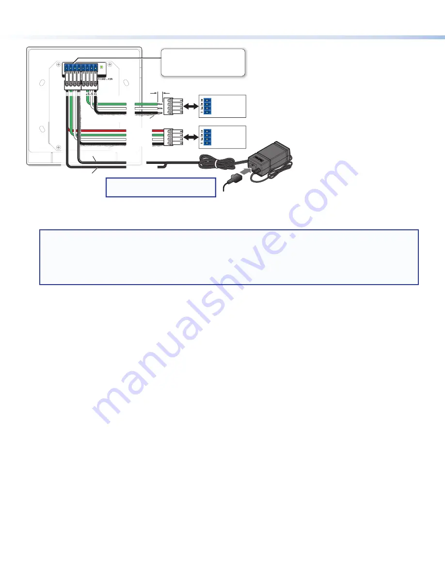
Figure 6.
Cabling EBP Panels with an Extron 12 VDC, 1 A Power Supply
Step 6: Configure the System
NOTES:
•
System configuration requires an IP network connection to the IPCP Pro. See the
IPCP Pro Series User Guide
for
information about the control processors and their ports.
•
EBP bus ID DIP switches should be set prior to uploading the configuration to the IPCP Pro.
•
See the
Global Configurator Help
file as needed for step-by-step instructions and detailed information. The help file for
GC includes an introduction to the software, and how to start a project and configuration.
1.
Create a new Global Configurator Plus or Professional project and configure the controller and any eBUS devices. The
configuration tells the controller how its ports function; how to control other products; what to monitor; when to do things;
and whom to notify, how, and under what circumstances.
a.
Configure ports on the control processor.
•
Select device drivers and link them to each assigned port.
•
Configure settings (serial protocol, relay behavior, digital input, volume control settings) as needed.
b.
Set up monitors, schedules, macros, and local variables.
c.
Set up the eBUS button panel buttons: assign appropriate commands and actions, macros, timers, local variables
monitors, or feedback to the buttons.
2.
Save the project.
3.
Build and upload the system configuration to the control processor.
Step 7: Test and Troubleshoot
1.
Verify that the DIP switches on the EBPs are set to the desired address on each unit and that there are no DIP switch address
conflicts in the system. As mentioned in the rear panel features diagram in
on page 4, the
eBUS LED lights steadily (solid) when power and communication are present and there are no bus ID address conflicts.
2.
Verify that cables to and from the EBPs are wired the same at each end (pin 1 to pin 1, pin 2 to pin 2, and so forth).
3.
Test the system.
•
Press buttons on the EBPs and ensure the buttons light as desired and that the appropriate control commands or
functions are triggered.
•
Ensure that the audio output responds correctly to the
volume
knob or button. Also ensure that the volume LEDs light
correctly as you increase or decrease the audio gain.
4.
Make adjustments to wiring, bus ID address, or system configuration as needed. Remember that the rear panel ports and DIP
switches will not be accessible after the EBP is mounted. If needed, upload a revised configuration to the control processor.
If you have questions during installation and setup, call the
Extron S3 Sales & Technical Support Hotline
or the Extron S3
Control Systems Support Hotline (1.800.633.9877).


