5
Cabling
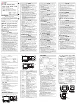
Attach cables using the diagrams in this section as a guide. Wiring is the same for all models. Connect a 4-pole captive screw
connector to each end of the cable, wiring both ends the same. In most cases the EBPs are powered by the IPCP Pro control
processor that provides the eBUS signal. Power is carried on the V+ pin of each eBUS connection.
Extron STP20-2/1000 or STP20-2P/1000 cable is recommended for eBUS connections.
G
-S
+S
+V
Ground
+
Signal
-
Signal
+
12 VDC
Black
and
Drains
Green
White
Red
G
-S
+S
+V
Drain Wires
Figure 4.
Basic eBUS Connector Wiring and Cable Color Code
EBPs that are relatively far from the control processor (see the
EBP 100 and EBP 200 User Guide
for details)
can be connected to an optional Extron PS 1220EB eBUS power inserter, or an Extron 12 VDC desktop power supply (Extron part
28-071-57LF) as shown in the following diagrams.
ATTENTION:
•
Always use a power supply supplied or specified by Extron. Use of an unauthorized power supply voids all regulatory
compliance certification and may cause damage to the supply and the unit.
•
Utilisez toujours une source d’alimentation fournie par Extron. L’utilisation d’une source d’alimentation non autorisée
annule toute conformité réglementaire et peut endommager la source d’alimentation ainsi que l’unité.
•
If not provided with a power supply, this product is intended to be supplied by a UL Listed power source marked
“Class 2” or “LPS” and rated output 12 VDC, minimum 1.0 A.
•
Si ce produit ne dispose pas de sa propre source d’alimentation électrique, il doit être alimenté par une source
d’alimentation certifiée UL de classe 2 ou LPS et paramétré à 12 VDC et 1,0 A minimum.
•
Unless otherwise stated, the AC/DC adapters are not suitable for use in air handling spaces or in wall cavities.
•
Sauf mention contraire, les adaptateurs AC/DC ne sont pas appropriés pour une utilisation dans les espaces d’aération
ou dans les cavités murales.
•
The installation must always be in accordance with the applicable provisions of National Electrical Code ANSI/NFPA 70,
article 725 and the Canadian Electrical Code part 1, section 16. The power supply shall not be permanently fixed to
building structure or similar structure.
•
Cette installation doit toujours être en accord avec les mesures qui s’applique au National Electrical Code ANSI/
NFPA 70, article 725, et au Canadian Electrical Code, partie 1, section 16. La source d’alimentation ne devra pas être
fixée de façon permanente à une structure de bâtiment ou à une structure similaire.
eBUS 24 WATTS MAX
100-240V 50-60Hz
0.6A MAX
+ V + S
G
– S
+ V + S
G
– S
+ V + S
G
– S
+ V + S
G
– S
+ V + S
G
– S
+ V + S
G
– S
eBUS port
on an EBP or
other eBUS
endpoint
device
+
V
+
S
G
– S
PWR OUT = 6W
V
C G
VOL
POWER
12V
1.0A MAX
G
Tx Rx
RTS CTS
COM 1
3
1
2
4 G
DIGITAL I/O
G
Tx Rx
COM 2
-S
+V +S
G
eBUS
C
1
2
RELAYS
S G
IR/S
LAN
IPCP PRO 250
MAC: 00-05-A6-
XX-XX-XX
S/N: ####### E######
IPCP Pro
X
G
-S
+S
G
-S
+S
G
-S
+S
+V
Ground
+
Signal
-
Signal
+
12 VDC
Tie drain wires
to ground.
G
-S
+S
X
G
-S
+S
+V
eBUS Connections
• Connect up to five (5) eBUS
endpoint devices to the PS 1220EB.
• Wire the connectors the same at
both ends.
• All ports are identical and
interchangeable.
Power Input
(100-240 VAC,
50-60 Hz)
PS 1220EB
ATTENTION:
Do NOT connect the power
pin to any device that is already powered
by the IPCP Pro control processor or by
an additional power supply.
3/16" (5 mm) Max.
EBP
eBUS
Panel(s)
Figure 5.
Cabling an eBUS System with an PS 1220EB Power Inserter
ATTENTION:
•
Always use a power supply
supplied or specified by Extron.
Use of an unauthorized power
supply voids all regulatory
compliance certification and
may cause damage to the
supply and the unit.
•
Utilisez toujours une source
d’alimentation fournie par
Extron. L’utilisation d’une
source d’alimentation non
autorisée annule toute
conformité réglementaire et
peut endommager la source
d’alimentation ainsi que l’unité.
•
If not provided with a power
supply, this product is intended
to be supplied by a UL Listed
power source marked “Class 2”
or “LPS” and rated output
12 VDC, minimum 1.0 A.
•
Si ce produit ne dispose pas de
sa propre source d’alimentation
électrique, il doit être alimenté
par une source d’alimentation
certifiée UL de classe 2 ou LPS
et paramétré à 12 VDC et 1,0 A
minimum.
•
Unless otherwise stated,
the AC/DC adapters are not
suitable for use in air handling
spaces or in wall cavities.
•
Sauf mention contraire, les
adaptateurs AC/DC ne sont pas
appropriés pour une utilisation
dans les espaces d’aération ou
dans les cavités murales.
•
The installation must always
be in accordance with the
applicable provisions of
National Electrical Code ANSI/
NFPA 70, article 725 and the
Canadian Electrical Code
part 1, section 16. The power
supply shall not be permanently
fixed to building structure or
similar structure.
•
Cette installation doit toujours
être en accord avec les
mesures qui s’applique au
National Electrical Code ANSI/
NFPA 70, article 725, et au
Canadian Electrical Code,
partie 1, section 16. La source
d’alimentation ne devra pas
être fixée de façon permanente
à une structure de bâtiment ou
à une structure similaire.