background image

8. Propeller and spinner

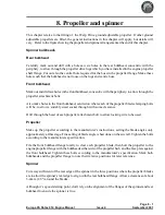
This chapter relates to the fitting of the Warp Drive ground adjustable propeller. If other ground
adjustable propellers are fitted, the general instructions in this chapter will apply, but details will
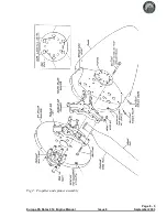
vary. Refer to the figure showing the propeller and spinner arrangement at the end of this chapter.

Spinner bulkheads

Rear bulkhead

Carefully mark out and drill with a hole saw six holes in the rear bulkhead, concentric with the
periphery, to allow through the propeller drive lugs which you have installed in the engine propeller
shaft flange. Cut out also the central hole required for the boss in the propeller flange. Make these
holes such that the bulkhead is not loose on the lugs and centre boss.

Front bulkhead

Mark out and drill six holes in the front bulkhead, concentric with the periphery, to allow through the
propeller attachment bolts.

Also make holes in the front bulkhead, centred on where each of the propeller blade clamping bolts
will be, to allow a suitably sized socket through with some clearance.

Drill through the head of each propeller attachment bolt to allow locking wire to be used.

Propeller

Make up the propeller according to the manufacturer’s instructions, setting the blade angles only
approximately at this stage. Fine setting of blade angle is best done on the aircraft. Tighten the bolts
according to the manufacturers specification.

File the front bulkhead flange locally to clear each propeller blade, then bolt the propeller to the
engine propeller flange with the bulkheads either side of the propeller hub, and the face plate against
the front bulkhead. Tighten these bolts according to the manufacturer’s specification. Mark both
bulkheads and the propeller flange to note their relative positions for later reference.

Spinner

Cut away sufficient of the rear edge of the spinner in the three positions where the propeller blades
are to allow the spinner’s rear edge to align with the rear bulkhead flange. Allow a clearance of about
3-4mm (1/8") around the blades.

Although it’s a good starting point, don’t rely on the alignment of the flanges of the spinner and rear
bulkhead to ensure the spinner is true.

Page 8 - 1

Europa XS Rotax 914 Engine Manual

Issue 4

September 2001

Содержание Rotax 914

Страница 1: ...Europa XS Rotax 914 Installation Manual Europa XS Rotax 914 Engine Manual Issue 7 October 2004 ...

Страница 2: ...llation 2 Engine controls 3 Oil tank 4 Cooling duct and coolers 5 Fuel system 6 Engine cowlings 7 Access doors 8 Propeller and spinner 9 Commissioning the engine Annex A Final inspection checklist September 2002 Issue 5 Europa XS Rotax 914 Engine Manual ...

Страница 3: ...he tailpipe EX08 to be added to it The tailpipe is designed tobe clamped inposition See figure 1 Althoughthe tailpipe couldbe welded to the silencer for tri gear operators this is not recommended as it is often better to remove the tailpipe before fitting or removing the lower cowlings as otherwise the presence of the nose gear can make life difficult Engine mount fitting There are two mounting fr...

Страница 4: ...of at least 4 washers on each bolt Any washers that are not needed to act as positioning shims should be placed immediately under the nut Make a note of where and how many shim washers are used for later reference Note The 4 AN5 41 mounting bolts must be tightened fully to compress the rubber anti vibration mounts MT04 onto the steel spacers MT03 Caution It should be noted that before the two igni...

Страница 5: ...Page 1 3 Europa XS Rotax 914 Engine Manual Issue 7 March 2006 Fig 2 914 engine installation exploded view ...

Страница 6: ...mounted vertically on firewall on the cabin side in the position shown in figure 2 The four mounting bolts pass through the firewall with the nuts in front of it Since the thread length of the bolts is rather short it will be necessary to make the appropriate part of the firewall thinner Using a 20 mm 3 4 hole saw carefully drill through the forward skin and foam only Bond NAS1169C10 Tinnerman was...

Страница 7: ...e firewall with a 4 8 mm drill Fit two MS21047 3 anchor nuts on the cabin side riveting them with TAPK36BS rivets Fit the bracket to the firewall with two AN3 4A bolts The pressure sensors are fitted to the bracket with AN4 5A bolts and MS21042 4 stiffnuts Connect a length of 4 mm bore PVC tube to each of the pressure sensors The airbox sensor tube connects to the unused leg of a nylon T piece sit...

Страница 8: ...ugs suitable for the ground adjustable Warp Drive propeller supplied loose These are a light interference fit in the propeller flange with a relief on the forward part to assist in starting the insertion of them into the flange To complete the installation it will be necessary to pull them into position using a suitable bolt nut and washer with a spacer tube Ensure that the drive lugs are fitted w...

Страница 9: ...115 positions but a gate will need to be included in the slotted facia plate through which the throttle lever runs to set the 100 position Special purpose software is used with which to set the throttle stops details of which are to be found in the Rotax s 914 Engine Installation Manual Although there are two independent throttles and chokes there is only one throttle and one choke control in the ...

Страница 10: ...igure 3 ensuring the end fittings are free to pivot Thread the cables into the cable outers then install the lever into the housing as shown in figure 2 adjusting the lever friction as desired The friction should be sufficient to prevent the carburettor throttle lever spring from opening the throttle automatically and this can be done after final assembly Cover the opening in the side of the housi...

Страница 11: ...able should emerge through the metal firewall on the opposite side to the carburettor that it will control Loop the cable up and aft towards the centre of the firewall then down into the bracket of the appropriate carburettor Loosely secure the two cables where they cross Insert the cable inner into the nipple on the carburettor throttle lever which is sprung to its full open position Settingthe t...

Страница 12: ...gh the metal firewall as do the throttle cables Loop these cables forward over the top of the engine so that they enter the 90 elbow guides mounted on the carburettor from the front Rotate the elbows so that the cables enter them as straight as possible Push the cables into the carburettor cable guides and secure the cables to the choke levers using the solderless nipples Ensure that the choke kno...

Страница 13: ...ction Recent Rotax engines have modified ignition shorting cable connections The photographs in figure 4 are self explanatory Page 2 5 Europa XS Rotax 914 Engine Manual Issue 10 November 2007 Fig 4 Ignition shoring cables connection ...

Страница 14: ...INTENTIONALLY BLANK Page 2 6 November 2007 Issue 10 Europa XS Rotax 914 Engine Manual ...

Страница 15: ...ure 1 Bending can be done by clamping the steel between lengths of wood in a vice Try to avoid a sharp bend radius a 10mm 3 8 radius is ideal Makea 90 anglebracket from thenarrow stripshownon thetemplate andrivet it to the topright port side using TLPD424BS rivets it should fit on top of the footwell Bracket installation Arranging the bracket with the upper lug fitting under the oil tank lid faste...

Страница 16: ...he hoses to the tank as shown in figure 2 Oil tank vent The vent from the oil tank allows an oil mist to escape to atmosphere It is not unusual to run the vent line to the bottom of the cowling however if you do this don t position the end of the tube such that it will be in the airstream whilst flying This could cause low pressure at the end of the tube to suck more oil from the tank than it shou...

Страница 17: ...anged one behind the other with the radiator in front of the oil cooler The duct is open at the bottom and uses the inside of the bottom cowling as the lower seal Duct Figures 1 shows the assembly of the aluminium duct from the individual components Page 4 1 Europa XS Rotax 914 Engine Manual Issue 4 September 2001 Fig 1 Assembly of cooling duct ...

Страница 18: ...de a clearance underneath the exhaust silencer of approximately 5 mm and be arranged to fit the air intake opening in the lower cowling See figure 2 A single AN3 5A bolt screws the side of the duct onto the inside face of the footwell using an MS21047 3 anchor nut installed in reverse into the footwell using TAPK 36 BS rivets to make it nearly flush the brackets CD4 and CD5 are then bolted to the ...

Страница 19: ...Figure 3 illustrates the mounting of the duct and the coolers Page 4 3 Europa XS Rotax 914 Engine Manual Issue 4 September 2001 Fig 3 Installation of duct and coolers ...

Страница 20: ...ne right angled Fit these so that the straight fitting is on the starboard side Toimprove oil coolinginhot climates the oil cooler can beloweredapproximately2 50mm so that it fits against the lower cowling use longer bolts with appropriate spacers In this case the blanking plate fitted below the radiator will not be needed Fordetails ofthe oil system connections seethe schematicviewat figure 9at t...

Страница 21: ... of the engine a compartment is made using parts CD6 and CD7 the lower cowling closing the bottom see the exploded diagram figure 6 The diagram shows what holes will be required in the compartment Not all the holes are pre cut Photographs figures 7 and 8 illustrate a completed installation First rivet parts CD6 and CD7 together using TAPD46BS rivets Position the assembly against the starboard foot...

Страница 22: ...Page 4 6 September 2001 Issue 4 Europa XS Rotax 914 Engine Manual Fig 7 Top view of air filter chamber Fig 6 Air filter chamber detail ...

Страница 23: ...ather hose should be routed so it can continuously drain Arranging it so that it vents close to the air filter will cause most of the oil mist to be ingested into the engine and so reduce the amount which would otherwise run down the fuselage Ensure that it doesn t exhaust such that oil can get onto the brake disc The wastegate cable needs to loop through the compartment to avoid sharp bends which...

Страница 24: ...Page 4 8 September 2001 Issue 4 Europa XS Rotax 914 Engine Manual Fig 9 Schematic view of oil cooling system ...

Страница 25: ...of the various fuel system fittings Whilst the pump is not installed either solder extension wires to the existing ones or attach connectors for later use Inline filters The in line filters are to be connected between the selector valve and the fuel pumps Before mounting the filters into the fuel system it is necessary to incorporate a safety spring in each Without this spring it is just possible ...

Страница 26: ... valve The return line is then fitted to this T piece Fuel sight gauge calibration When the time comes to calibrate the fuel sight gauge you will need to start with the Reserve side full and only unuseable fuel in the Main side Set the aircraft level to simulate level flight then pour in sufficient fuel to ensure that 2 or 3 litres will go over the tank tunnel and into the Main side 15 litres shou...

Страница 27: ...Page 5 3 Europa XS Rotax 914 Engine Manual Issue 8 November 2004 Fig 1 Schematic diagram of fuel system fittings ...

Страница 28: ...Page 5 4 November 2004 Issue 8 Europa XS Rotax 914 Engine Manual Fig 2 Fuel system ...

Страница 29: ...e first of these jobs leave a small flange about 4 5mm 3 16 around the outlet to give it some stiffness 2 Opening the up the side cooling gills 3 Opening for the NACA scoop in the lower cowling To prevent the end of the inlet ramp contacting the air filter it may be necessary to file away the rear of the ramp 4 Cutting the hole in the upper and lower cowlings for the propeller shaft Initially cut ...

Страница 30: ...a 3 2 mm 1 8 drill Use clecos through some of the holes to hold the cowlings together Since the engine has already been set tothe correct position relative tothe fuselage the cowlings will be set so that the front circular flat area is concentric with the engine propeller flange Trim the rear edge of the cowlings as required to ensure a good fit to the fuselage with the front face concentric with ...

Страница 31: ...hor nuts are to be located will vary depending on their position a selection of 3 2 mm diameter countersink rivets areprovided Usethe shortest rivet that youcanforattachingeachanchornut intothe fuselage Countersink the outside face of all the holes of the upper cowling and the rearmost holes only of the lower cowling except the upper rear holes to allow the Tinnerman washers to lie flat against th...

Страница 32: ...INTENTIONALLY BLANK Page 6 4 November 2004 Issue 8 Europa XS Rotax 914 Engine Manual ...

Страница 33: ...blade to minimise the gap around it The scribed outline of a NACA inlet on the top cowling is for the Rotax 912 S engine You can ignore this Flange Reposition the door panels in the openings as accurately as possible and tape them temporarily in place from the outside Scuff sand the inside of the cowling around the door panels Cover the door panel with plastic sheeting to act as a release agent La...

Страница 34: ...ersinking the outside of the door panel first rivet the latch to the door panel using TAPK 33 BS rivets Hinges Cut a piece of 20001 3 hinge to be 75mm 3 long for each door and file a clearance cut out for the hinge pivot in both the door panel and cowling at the other side to the latch Trim away the flange locally to clear the latch Bond and rivet the hinge in place using countersunk TLPK 424 BS r...

Страница 35: ...ugh with some clearance Drill through the head of each propeller attachment bolt to allow locking wire to be used Propeller Make up the propeller according to the manufacturer s instructions setting the blade angles only approximately at this stage Fine setting of blade angle is best done on the aircraft Tighten the bolts according to the manufacturers specification File the front bulkhead flange ...

Страница 36: ...e circumference Drill through boththe spinner and the front bulkheadflange with a 4 8mm drill at thesix centres then install MS21047 3 anchor nuts to the bulkhead using TAPK 33 BS rivets The spinner is now ready for installation with screws however the propeller pitch must be set beforehand Propeller pitch The relationship between propeller pitch and aircraft performance is something which will va...

Страница 37: ...the blade angle is set tighten the bolts 20 inch pounds at a time starting with the bolts nearest the centre and working outwards After tightening the bolts check that the blade angle setting has not altered Turn the propeller to the next blade and repeat the sequence After the last blade has been set check that the others have not been disturbed Don t accept a mismatch between blades of an angle ...

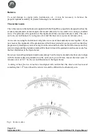
Страница 38: ...the alignment of the graduations of both inner and outer scales you will see that they progressively misalign as you move away from the zero and then after the 30 of the inner scale they start to realign until the graduation marked 60 is back in line with a graduation on the outer scale See the first illustration in the figure below If you now look at the graduation mark representing 15 on the inn...

Страница 39: ...Page 8 5 Europa XS Rotax 914 Engine Manual Issue 6 September 2003 Fig 2 Propeller and spinner assembly ...

Страница 40: ...INTENTIONALLY BLANK Page 8 6 September 2002 Issue 5 Europa XS Rotax 914 Engine Manual ...

Страница 41: ...72 or 966473 these engines have a TCU at rev 4 5 and a dongle will be required the appropriate software is 4 5 Newer engines have a TCU part number 966741 a dongle is not required and the TCU and software are at rev 4 6 The software required must be installed in the PC The cable and software are available on hire from Europa With the master switch of the aircraft on run the program detailed instru...

Страница 42: ... If the pressure does not rise stop the engine straight away and prime the oil system again CAUTION When conducting any checks do not run the engine at high power settings without having suitably secured the aircraft against unwanted movement For monowheel aircraft it is strongly advised to tie the tailwheel down to prevent the possibility of nosing over After priming make sure that all oil connec...

Страница 43: ...litre in not more than 87 seconds 1 US quart in 82 seconds Do the same check with the other pump and finally with both pumps Repeat these checks with the fuel selector on Reserve and record the fuel flows that were achieved Note Quantity pumped litres time seconds x 3600 litres hour If using quarts use the same formula but don t forget to divide the result by 4 to obtain gallons hour If you cannot...

Страница 44: ...INTENTIONALLY BLANK Page 9 4 September 2002 Issue 5 Europa XS Rotax 914 Engine Manual ...

Страница 45: ...bulletins issued to date The engine may be new but abulletinortwomayhavebeenissuedsincetheenginewas built or sincepurchase General Check incorporation of Mod 72 Undercarriage Mounting Frame Reinforcement Check clearance between the engine mounting frame and the moving parts CS21 of the rudder and cable installation Check that the cooling opening for the turbocharger is present in the cooling duct ...

Страница 46: ...tion boxes Check that an earth wire is connected to the above p clip Operation With throttle fully closed switch on master switch and observe the turbo wastegate lever The lever should cycle open and closed closed is with the cable pulling the lever Check that the wastegate is fully closed Check that the desired maximum static rpm is achieved for fixed pitch propellers see chapter 8 Ensure that th...

Страница 47: ... register Rotax engines are designed to run on Mogas Please note that if you intend to use Mogas in your aircraft it is necessary to apply for permission from the L A A Europa XS Rotax 914 Engine Manual March 2008 Page 10 3 ...

Отзывы: