Drill also a 4.8 mm hole in each flange for mounting bolts. Open up the hole on the starboard side of
the housing to allow a socket spanner through.
Assembly
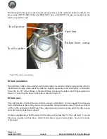
Install the cable outers through the two holes in the housing and clamp them in position using the
nyloc nut with an AN960-416L washer each side of the fibreglass. Assemble the two cables to the
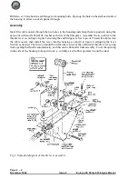
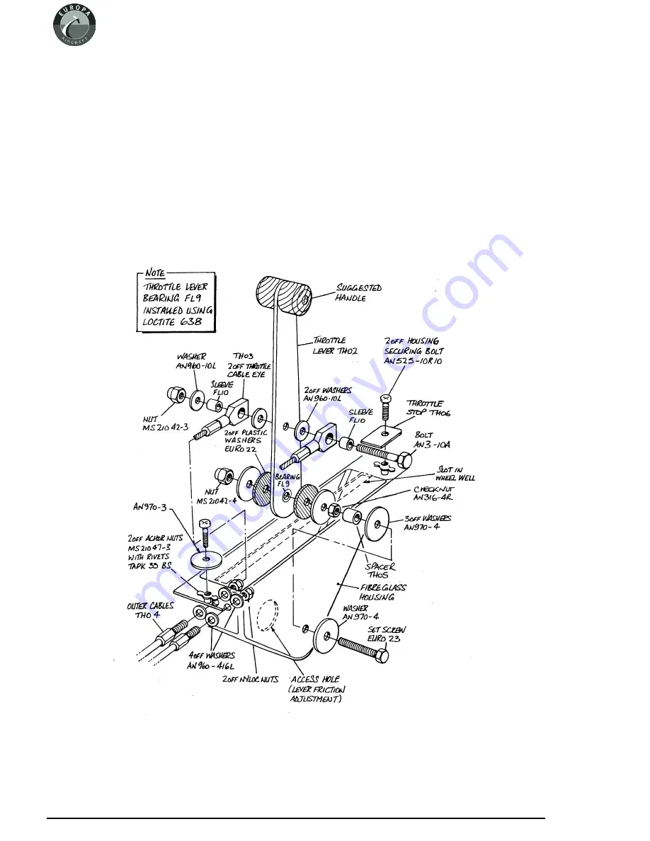
throttle lever according to figure 3 ensuring the end fittings are free to pivot. Thread the cables into
the cable outers, then install the lever into the housing as shown in figure 2, adjusting the lever
friction as desired. The friction should be sufficient to prevent the carburettor throttle lever spring
from opening the throttle automatically, and this can be done after final assembly. Cover the opening
in the side of the housing to keep dirt out - a suitably sized rubber grommet would be ideal.
Page 2 - 2
November 2004
Issue 8
Europa XS Rotax 914 Engine Manual
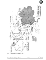
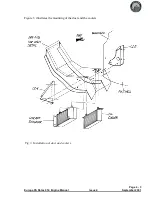
Fig 2. Exploded diagram of throttle lever assembly.
Содержание Rotax 914
Страница 1: ...Europa XS Rotax 914 Installation Manual Europa XS Rotax 914 Engine Manual Issue 7 October 2004 ...
Страница 14: ...INTENTIONALLY BLANK Page 2 6 November 2007 Issue 10 Europa XS Rotax 914 Engine Manual ...
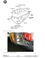
Страница 24: ...Page 4 8 September 2001 Issue 4 Europa XS Rotax 914 Engine Manual Fig 9 Schematic view of oil cooling system ...
Страница 28: ...Page 5 4 November 2004 Issue 8 Europa XS Rotax 914 Engine Manual Fig 2 Fuel system ...
Страница 32: ...INTENTIONALLY BLANK Page 6 4 November 2004 Issue 8 Europa XS Rotax 914 Engine Manual ...
Страница 39: ...Page 8 5 Europa XS Rotax 914 Engine Manual Issue 6 September 2003 Fig 2 Propeller and spinner assembly ...
Страница 40: ...INTENTIONALLY BLANK Page 8 6 September 2002 Issue 5 Europa XS Rotax 914 Engine Manual ...
Страница 44: ...INTENTIONALLY BLANK Page 9 4 September 2002 Issue 5 Europa XS Rotax 914 Engine Manual ...

