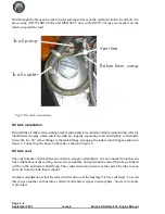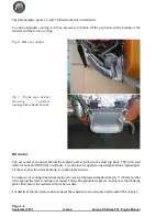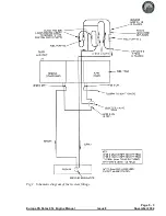
Connect one side of the oil cooler to the 90° union fitted to the oil tank, and the other side of the oil
cooler to the oil pump inlet using the pre-formed hose C06. Trim the short straight section to attach
the hose to the pump inlet so that the hose is the maximum distance from the right hand exhaust pipe.
The hose runs aft and up to go over the rear cylinder water hose, under the starter motor and inside the
ring mount, thence it goes down to the radiator on the opposite (port) side.
Connect the oil sump drain at the bottom of the engine to the tangential fitting on the oil tank. For this
connection use the hose marked “Conti” supplied with the Rotax engine. Set the banjo union at the
bottom of the engine to point to the right and approximately 30° forwards. The hose curves
immediately aft and up to go over the rear cylinder’s water hose, under the starter motor and inside
the engine ring mount; it then loops up to the tank.
Radiator
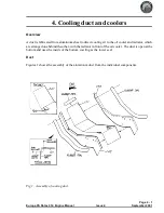
The radiator is bolted to the side plates of the cooling duct by two AN4-5A bolts and MS21042-4 nuts
each side.
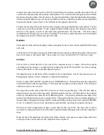
A short hose, C05, leads from one port of the radiator to the engine coolant pump outlet, and a longer
hose, C04, leads to the header tank. These hoses are to be secured with 25-35 mm hose clips.
Air filter
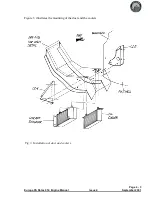
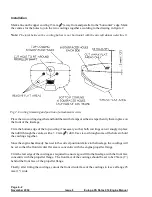
The air filter is fitted directly to the end of the compressor and, to isolate it from the general
environment of the engine, a compartment is made using parts CD6 and CD7, the lower cowling
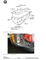
closing the bottom, see the exploded diagram figure 6.
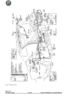
The diagram shows what holes will be required in the compartment. Not all the holes are pre-cut.
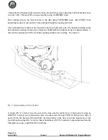
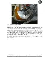
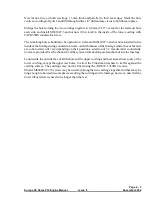
Photographs, figures 7 and 8, illustrate a completed installation.
First rivet parts CD6 and CD7 together using TAPD46BS rivets. Position the assembly against the
starboard footwell with the top surface 13 cm below the top surface of the footwell. This will allow
sufficient room for the oil tank.
The large hole in the side of the CD6 is for the air filter to pass through. This will also help in
determining the location of the assembly. Drill through the rear face of CD6 and into the footwell
with a 4.8 mm drill for the three AN525-10R8 fixing bolts . Temporarily attach the assembly to the
footwell and check that the lower cowling will fit. The gap between the lower cowling and edges of
the assembly is bridged with strips of fabric reinforced rubber sealing riveted to it using TAPD46BS
rivets. It is probably best to leave attaching the seal until the cowlings are properly attached.
With the air filter compartment in place, check that the filter itself fits. On early kits it will be
necessary to enlarge the hole to allow the filter to pass through and engage fully onto the compressor
inlet.
Holes for the oil breather hose (from the neck of the oil tank), static pressure sensor tube and for the
wastegate cable to enter and exit the compartment are required.
Page 4 - 5
Europa XS Rotax 914 Engine Manual
Issue 4
September 2001
Содержание Rotax 914
Страница 1: ...Europa XS Rotax 914 Installation Manual Europa XS Rotax 914 Engine Manual Issue 7 October 2004 ...
Страница 14: ...INTENTIONALLY BLANK Page 2 6 November 2007 Issue 10 Europa XS Rotax 914 Engine Manual ...
Страница 24: ...Page 4 8 September 2001 Issue 4 Europa XS Rotax 914 Engine Manual Fig 9 Schematic view of oil cooling system ...
Страница 28: ...Page 5 4 November 2004 Issue 8 Europa XS Rotax 914 Engine Manual Fig 2 Fuel system ...
Страница 32: ...INTENTIONALLY BLANK Page 6 4 November 2004 Issue 8 Europa XS Rotax 914 Engine Manual ...
Страница 39: ...Page 8 5 Europa XS Rotax 914 Engine Manual Issue 6 September 2003 Fig 2 Propeller and spinner assembly ...
Страница 40: ...INTENTIONALLY BLANK Page 8 6 September 2002 Issue 5 Europa XS Rotax 914 Engine Manual ...
Страница 44: ...INTENTIONALLY BLANK Page 9 4 September 2002 Issue 5 Europa XS Rotax 914 Engine Manual ...

