5. Fuel system
The installation of the fuel system described in the fuselage manual takes the fuel line as far as the
fuel selector valve. After the fuel has passed through the fuel valve the line connects to twin in-line
filters which are transparent and so aid visual detection of contamination. From the filters the lines
run to the twin electric pump inlets. The electric pumps are pilot activated, and are duplicated as the
Rotax 914 engine is not fitted with a mechanical pump. From the electric pumps the fuel lines join
again . This line is connected to the inlet of the fuel pressure regulator on the top rear of the engine. A
further line from the regulator takes a small flow of fuel back to the starboard side of the fuel tank.
The engine connection to this line incorporates an already fitted restrictor, to allow a flow of fuel to
prevent fuel vapourisation in hot conditions.
Installation
Electric fuel pumps
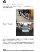
The electric pumps (supplied with the engine) are to be mounted in the port underfloor chamber
situated in the baggage bay floor.
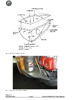
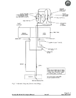
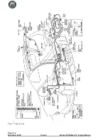
Refer to the schematic diagram on page 3 and drawing on page 4 for details of the various fuel system
fittings.
Whilst the pump is not installed, either solder extension wires to the existing ones or attach
connectors for later use.
Inline filters
The in-line filters are to be connected between the selector valve and the fuel pumps.
Before mounting the filters into the fuel system it is necessary to incorporate a safety spring in each.
Without this spring it is just possible for the knurled nut, if it comes loose, to cover most of the fuel
flow holes’ area and so limit fuel flow, which could result in engine failure.
Unscrew the end fitting at the end which has the 2 fuel flow holes and the knurled nut (the inlet end).
Fit t he spring part number LC042G-2 over the fuel flow holes and, with it butting up against the
knurled nut, refit the end fitting.
The outlet of the selector valve points aft; connect a length of the 8mm fuel hose to the outlet fitting
HFSB 8-4N (which should already be fitted to the selector valve), and route it aft through the tunnel,
under the fuel tank and into the port underfloor chamber.
Connect the filters, fuel pumps and non-return valves according to the fuel schematic on page 3,
figure 1. Arrange for the fuel filters to be positioned above the pumps - this will assist when filter
cleaning is carried out.
Page 5 - 1
Europa XS Rotax 914 Engine Manual
Issue 8
November 2004
Содержание Rotax 914
Страница 1: ...Europa XS Rotax 914 Installation Manual Europa XS Rotax 914 Engine Manual Issue 7 October 2004 ...
Страница 14: ...INTENTIONALLY BLANK Page 2 6 November 2007 Issue 10 Europa XS Rotax 914 Engine Manual ...
Страница 24: ...Page 4 8 September 2001 Issue 4 Europa XS Rotax 914 Engine Manual Fig 9 Schematic view of oil cooling system ...
Страница 28: ...Page 5 4 November 2004 Issue 8 Europa XS Rotax 914 Engine Manual Fig 2 Fuel system ...
Страница 32: ...INTENTIONALLY BLANK Page 6 4 November 2004 Issue 8 Europa XS Rotax 914 Engine Manual ...
Страница 39: ...Page 8 5 Europa XS Rotax 914 Engine Manual Issue 6 September 2003 Fig 2 Propeller and spinner assembly ...
Страница 40: ...INTENTIONALLY BLANK Page 8 6 September 2002 Issue 5 Europa XS Rotax 914 Engine Manual ...
Страница 44: ...INTENTIONALLY BLANK Page 9 4 September 2002 Issue 5 Europa XS Rotax 914 Engine Manual ...

