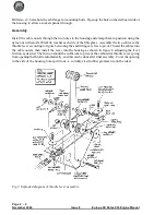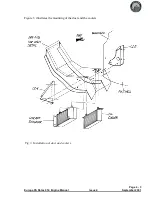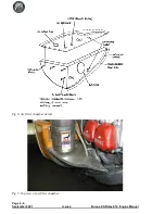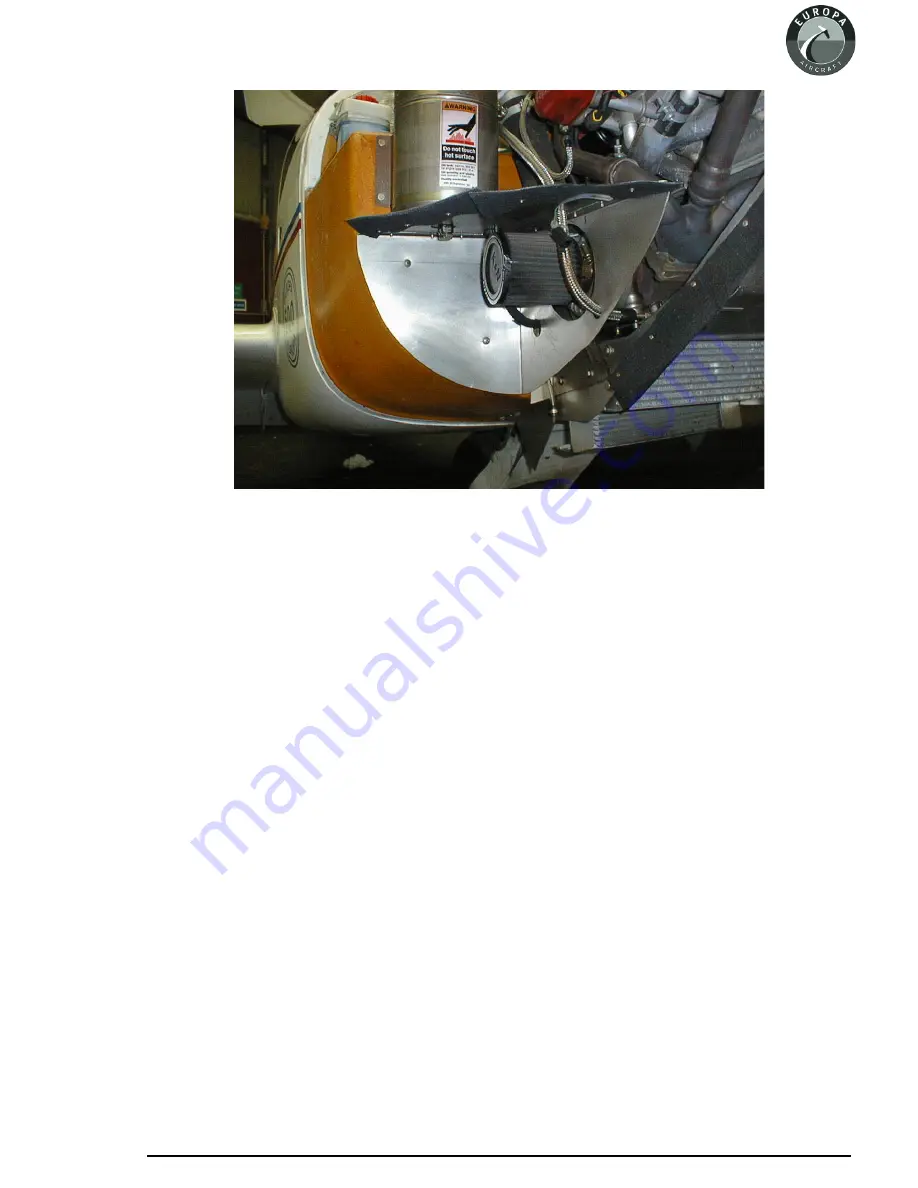
Indication of where these holes should be are shown in the diagram, however actual positions are
best determined on the actual aircraft. Remember to use grommets in the holes to avoid chafing.
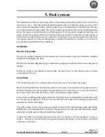
After final fitting of the air filter compartment secure the static pressure sensor tube so that its end is
about 4 - 5 cm within it. The oil breather hose should be routed so it can continuously drain.
Arranging it so that it vents close to the air filter will cause most of the oil mist to be ingested into the
engine and so reduce the amount which would otherwise run down the fuselage. Ensure that it
doesn’t exhaust such that oil can get onto the brake disc.
The wastegate cable needs to loop through the compartment to avoid sharp bends which would
inhibit its operation.
Page 4 - 7
Europa XS Rotax 914 Engine Manual
Issue 4
September 2001
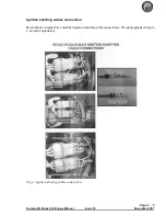
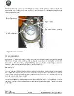
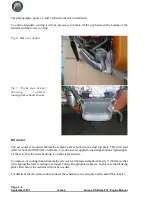
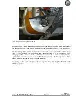
Fig 8. Lower view of air filter chamber.
Содержание Rotax 914
Страница 1: ...Europa XS Rotax 914 Installation Manual Europa XS Rotax 914 Engine Manual Issue 7 October 2004 ...
Страница 14: ...INTENTIONALLY BLANK Page 2 6 November 2007 Issue 10 Europa XS Rotax 914 Engine Manual ...
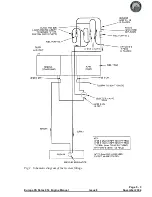
Страница 24: ...Page 4 8 September 2001 Issue 4 Europa XS Rotax 914 Engine Manual Fig 9 Schematic view of oil cooling system ...
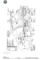
Страница 28: ...Page 5 4 November 2004 Issue 8 Europa XS Rotax 914 Engine Manual Fig 2 Fuel system ...
Страница 32: ...INTENTIONALLY BLANK Page 6 4 November 2004 Issue 8 Europa XS Rotax 914 Engine Manual ...
Страница 39: ...Page 8 5 Europa XS Rotax 914 Engine Manual Issue 6 September 2003 Fig 2 Propeller and spinner assembly ...
Страница 40: ...INTENTIONALLY BLANK Page 8 6 September 2002 Issue 5 Europa XS Rotax 914 Engine Manual ...
Страница 44: ...INTENTIONALLY BLANK Page 9 4 September 2002 Issue 5 Europa XS Rotax 914 Engine Manual ...

