EUROCOM 5600D Monte Carlo Скачать руководство пользователя страница 50

Using The Computer

LED Indicators 2 - 7

2

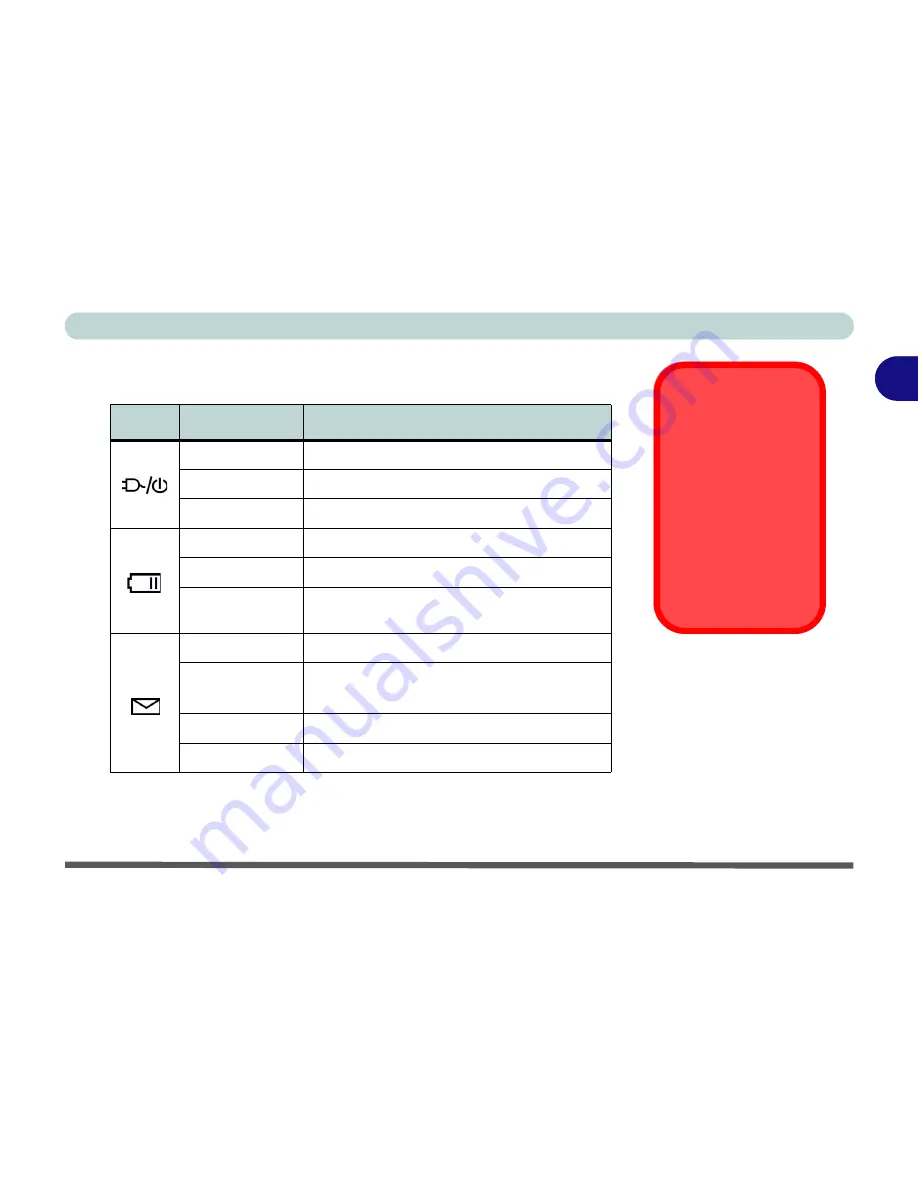
LED Power & Auto Mail Indicators

Icon

Color

Description

Yellow

AC Power is plugged in

Green

The computer is on

Blinking Green

The system is in the configured standby mode

Yellow

The battery is being charged

Green

The battery is fully charged

Blinking Yellow

The battery has reached critically low power 

status

Blinking Green

New mail has arrived

Fast Blinking 

Green

New mail has arrived from users defined in the 

Special Group in the Auto Mail Checker

Orange

The 

secondary*

 battery is being charged

Green

The 

secondary* 

battery is fully charged

Low Battery Warning

When the battery is
critically low, immedi-
ately connect the AC
adapter to the comput-
er or save your work,
otherwise, the un-
saved data will be lost
when the power is de-
pleted.

*Note

: The secondary

battery is 

optional

, de-

pending upon the con-
figuration purchased.

Table 2 - 2

LED Power & 

Automail 

Indicators

Содержание 5600D Monte Carlo

Страница 1: ......

Страница 2: ...of this publication except for copies kept by the user for backup purposes Brand and product names mentioned in this publication may or may not be copyrights and or registered trademarks of their res...

Страница 3: ...If this equipment does cause harmful interference to radio or television reception which can be determined by turning the equipment off and on the user is encouraged to try to correct the interferenc...

Страница 4: ...hone other than a cordless type during an electrical storm There may be a remote risk of electrical shock from lightning 3 Do not use the telephone to report a gas leak in the vicinity of the leak 4 U...

Страница 5: ...any kind of heating element This is an electrical appliance If water or any other liquid gets into it the com puter could be badly damaged Do not expose the computer to any shock or vibration Do not...

Страница 6: ...nd don t forget to save your work Remember to periodically save your data as data may be lost if the battery is depleted 5 Take care when using peripheral devices Do not turn off the power until you p...

Страница 7: ...qualified electrician install one When you want to unplug the power cord be sure to disconnect it by the plug head not by its wire Make sure the socket and any extension cord s you use can support th...

Страница 8: ...or discarded Keep the battery away from metal appliances Affix tape to the battery contacts before disposing of the battery Do not touch the battery contacts with your hands or metal objects Battery D...

Страница 9: ...icing to authorized service personnel Unplug the computer from the power supply Then refer servicing to qualified service personnel under any of the following con ditions When the power cord or AC DC...

Страница 10: ...es from 100 to 240 volts so you won t need a second voltage adapter However check with your travel agent to see if you need any socket adapters 6 Put the notebook in its carrying bag and secure it wit...

Страница 11: ...ta Pass your computer and disks around the devices Ask security officials to hand inspect them you may be asked to turn it on Note Some airports also scan luggage with these devices Fly safely Most ai...

Страница 12: ...ms wrists and hands in a relaxed position Your knees should be slightly higher than your hips Place your feet flat on the floor or on a footrest if necessary Use a chair with a back and adjust it to s...

Страница 13: ...n the display to avoid glare or reflections from overhead lighting or outside sources of light Keep the display screen clean and set the brightness and contrast to levels that allow you to see the scr...

Страница 14: ...now Your Computer 1 4 Model Types 1 5 CPU Type 1 5 Video Card 1 6 USB Port Type 1 6 Top View with LCD Panel Closed 1 8 Top View with LCD Panel Open 1 9 LCD Panel 1 10 LED Power Auto Mail Indicators 1...

Страница 15: ...g of the Battery Pack 2 4 Turning on the Computer 2 5 LED Indicators 2 6 LED Status Indicators 2 6 LED Power Auto Mail Indicators 2 7 Auto Mail Checker 2 8 Special Group 2 10 The Hard Disk Drive 2 11...

Страница 16: ...Options 3 16 Conserving Power Individual Components 3 17 Turn off Monitor 3 17 Turn off Hard Disks 3 17 Conserving Power System 3 18 Hibernate Mode vs Shutdown 3 18 Standby Mode vs Hibernate Mode 3 18...

Страница 17: ...Professional 4 15 Chipset Win2000 4 15 Audio Win2000 4 15 Modem Win2000 4 16 LAN Win2000 4 17 Video Win2000 4 17 TouchPad Win2000 4 17 Hot Key Win2000 4 18 Auto Mail Win2000 4 18 Intel SpeedStep Win20...

Страница 18: ...ess 6 6 Upgrading the Device in Bay Two 6 8 Upgrading the System Memory 6 9 Memory Upgrade Process 6 10 Upgrading the Processor 6 14 Troubleshooting 7 1 Overview 7 1 Basic Hints and Tips 7 2 Backup an...

Страница 19: ...2 Memory A 2 BIOS A 2 LCD Options A 2 Display Models A B A 2 Display Model C A 3 Storage A 3 Audio A 3 PC Card A 3 Interface A 4 Communication A 4 Power Management A 4 Power Model A A 5 Power Model B...

Страница 20: ...refer to the Drivers Utilities on page 4 1 BI OS Utilities on page 5 1 and Upgrading The Computer on page 6 1 You may also find the notes marked with a of interest to you Beginners and Not So Advance...

Страница 21: ...ve their own manuals as do applica tions e g word processing spreadsheet and database programs If you have questions about the operating systems or programs then please consult the ap propriate manual...

Страница 22: ...e box Before you begin please follow the safety instruc tions in the Preface 1 Remove all packing materials CDs DVDs floppy disks and any PC Cards 2 Securely attach any peripherals you want to use wit...

Страница 23: ...Getting To Know Your Computer The following graphics will help you to become familiar with the basic func tions and to learn the location of the various ports and components of your computer Design D...

Страница 24: ...ypes on page A 1 for the full details on CPU types Only Model B supports mobile processors see Mobile CPU on page 3 15 and requires the installation of the Intel SpeedStep driver for Win 98SE Win ME a...

Страница 25: ...ver it is the same driver for both video card types USB Port Type For full details on the USB ports see Four USB Ports on page 1 21 Only Model C supports USB 2 0 and you may identify if your system is...

Страница 26: ...n Feature Model A Model B Model C CPUs Supported Intel Pentium 4 1 4 1 5 1 6 1 7 1 8 2 0 2 2 2 4GHz Intel Mobile Pentium 4 1 4 1 5 1 6 1 7 1 8 2 0GHz Intel Pentium 4 2 0 2 2 2 26 2 4 2 5 2 53 2 6 2 66...

Страница 27: ...to release the top cover 3 Lift the top cover to reveal the LCD panel and keyboard 4 Adjust the LCD panel to a comfortable viewing angle 5 The LED Power E Mail indicators show the power source and pow...

Страница 28: ...LCD Panel Open Figure 1 3 Top View with LCD Panel Open 1 LCD 2 LED Power E Mail Indicators 3 Close Cover Switch 4 Speakers 5 Hot Key buttons 6 LED Status Indicators 7 Power Button 8 Keyboard 9 TouchP...

Страница 29: ...of the computer The third indicator may be configured to give a visual confirmation when e mail is received in the default e mail program see Auto Mail Check er on page 2 8 Close Cover Switch This sw...

Страница 30: ...this button to turn your computer on or off see Turning on the Computer on page 2 5 This button may also be used as a suspend resume key once configured as such in the power management control panel...

Страница 31: ...ng device features a sensitive glide pad for precise movements It functions the same way as a two button mouse The right TouchPad button is the same as the right mouse button the left TouchPad button...

Страница 32: ...ce If the computer is running then control for all CDs is handed over to the oper ating system s software controller however the CD Player s volume controls can still be used to set the audio volume 2...

Страница 33: ...ord on your notebook computer with the built in microphone Sound Volume Adjustment How high the sound volume can be set using the volume control knob depends on the setting of the volume control withi...

Страница 34: ...ferred to as PCMCIA Refer to The PC Card Slot on page 2 17 for more information on the PC Card slot Vent This enables airflow to prevent the notebook from overheating 1 2 3 4 Figure 1 5 Left Side View...

Страница 35: ...ode FDD DVD ROM CD ROM CD RW and DVD ROM Combo drive CD RW Secondary battery pack Bay Two will have ONE of the following fixed CD devices depending on the configuration purchased DVD ROM CD ROM CD RW...

Страница 36: ...nding on the model you purchased There may also be another CD device in Bay One For more information on using the drive please refer to The CD DVD Device on page 2 13 1 CD ROM or DVD label to indicate...

Страница 37: ...2k SIR 4M bps FIR IrDA 1 1 compliant see Configuring the Infrared Settings for FIR on page 3 26 For further information please refer to the manual of the device you wish to connect Infrared Communicat...

Страница 38: ...SB Ports 7 RJ 11 Phone Jack 8 RJ 45 LAN Jack 9 S Video Connector 10 External Monitor CRT Port 11 Parallel Port 12 PS 2 Type Port 13 Vents 2 3 4 5 6 7 8 9 10 11 12 6 1 13 13 Overheating To prevent your...

Страница 39: ...s may be connected through this jack Note Set your system s volume to a reduced level before connecting to this jack S PDIF Out Port You can use this port for S PDIF Sony Philips Digital Interface For...

Страница 40: ...Port Type on page 1 6 High speed USB devices are usually only USB 2 0 compliant check the documentation which comes with your USB compliant peripheral Devices may be plugged into the computer and unp...

Страница 41: ...bling TV Display on page 3 13 External Monitor CRT Port Connect an external CRT monitor to this port to allow dual video or simulta neous display on the LCD and external CRT monitor see Display Device...

Страница 42: ...ating To prevent your com puter from overheating make sure nothing blocks the vent fan outlets while the com puter is in use Figure 1 9 Bottom View 1 Vent Fan Outlets 2 Device Bay One 3 Device Bay One...

Страница 43: ...optional 802 11b Wireless Networking solu tion If included the antennae and other components are not externally visible please check with your service representative If your configuration includes the...

Страница 44: ...rn more about your computer s features please read this chapter This chapter includes The Power Sources Turning on the Computer LED Indicators The Hard Disk Drive The Floppy Disk Drive The CD DVD Devi...

Страница 45: ...ill damage the computer and its components 1 Attach the AC adapter to the DC in jack on the left of the computer 2 Plug the AC power cord into an outlet then connect the AC power cord to the AC adapte...

Страница 46: ...tion you re using To increase battery life let the battery discharge completely before recharging We recommend leaving the battery inside the notebook at all times For more information on the battery...

Страница 47: ...ry When the computer is turned off but plugged into an electrical outlet battery charge time is less see LED Indicators on page 2 6 for information on the battery charge status Proper handling of the...

Страница 48: ...e Windows Control Panel to configure this feature Power Button as Standby or Hibernate Button If you are using a fully ACPI compliant OS such as Windows ME Windows 2000 Profes sional or Windows XP you...

Страница 49: ...omputer The LED Power Auto Mail Indicators are also visible when the top of your computer is closed LED Status Indicators Icon Color Description Green Floppy Hard disk CD Device activity Green Number...

Страница 50: ...inking Green New mail has arrived Fast Blinking Green New mail has arrived from users defined in the Special Group in the Auto Mail Checker Orange The secondary battery is being charged Green The seco...

Страница 51: ...give you notification when you receive new mail You must be online to receive this notification note that this program only supports the POP3 protocol and your default mail program does not need to b...

Страница 52: ...ptions for your mailserver name password pro gram and method s of notification Note Check with your Inter net Service Provider network administrator or Mail Service provid er for details on what to pu...

Страница 53: ...ble the Mail LED then the icon will flash when you receive new mail in your default mail program You may add the e mail addresses of those you wish to assign to your special group here The LED will th...

Страница 54: ...age on page A 3 The hard disk is accessible from the bottom of your computer under the device installed in Bay One as seen below Further details on removing and in serting the hard disk are available...

Страница 55: ...perly set in the BIOS refer to Boot Menu on page 5 16 Inserting Removing Floppy Disks When using the floppy drive always insert your floppy diskette with the label side facing up To remove the inserte...

Страница 56: ...orce for the disc to click onto the tray s spindle Gently push the CD DVD tray in until its lock clicks and you are ready to start The Busy Indicator will light up while data is being accessed or whil...

Страница 57: ...to the surface of the disc Do not store or place the CD or DVD in high temperature areas Do not use benzene thinner or other cleaners to clean the CD or DVD Do not bend the CD or DVD Do not drop or su...

Страница 58: ...altered even if you change your operating system or you use the module in another computer WinDVD Player Note WinDVD version 3 1 supports CPU speeds up to and including 2 4GB only WinDVD version 4 0...

Страница 59: ...e control panel as seen in DVD Regional Codes Windows XP on page 2 15 DVD Regional Coding Region Geographical Location 1 USA Canada 2 Western Europe Japan South Africa Middle East Egypt 3 South East A...

Страница 60: ...and Removing PC Cards Align the PC Card with the slot and push it in until it locks into place To remove a PC Card simply press the eject button next to the slot The PC Card Problem in Windows 98SE S...

Страница 61: ...installation steps Programming the Hot Keys Hot Key Function Activate the default e mail program Activate the default Internet browser Activate the user specified application e g Microsoft Word or Ex...

Страница 62: ...ect Setup from the menu and scroll to Application 1 and press Enter 3 An Open dialog box will appear on the screen 4 Browse to the directory where the desired application exe see the sidebar program e...

Страница 63: ...ys Description Fn F3 Turn audio on off Fn F4 Toggle between suspend resume state Fn F5 Decrease audio volume Fn F6 Increase audio volume Fn F7 Toggle between CRT LCD LCD and CRT Fn F8 Decrease LCD bri...

Страница 64: ...Fn key and the NumLk key to the top right of the keyboard You may check if Number Lock is en abled or not by looking at the LED status indicators see LED Status Indi cators on page 2 6 Special Charact...

Страница 65: ...Using The Computer 2 22 The Numeric Keypad 2 Function Keys and Numeric Keypad Figure 2 10 Function Keys Numeric Keypad...

Страница 66: ...to your computer either through the PS 2 interface or one of the USB ports The TouchPad buttons function in much the same way as a two button mouse The central button may be configured to function as...

Страница 67: ...TouchPad driver icon on the taskbar You may then configure the TouchPad tracking buttons and Rocker Switch etc to your preferences You will find further information on this at www synaptics com Figure...

Страница 68: ...a USB interface connection There are four USB ports on your notebook computer and you may use any one of the ports to connect the printer Install Instructions 1 Set up the printer according to its ins...

Страница 69: ...packing paper tray toner ink cartridge etc 2 Attach the parallel cable to the printer 3 Connect the printer s parallel cable to the parallel port at the rear of the computer see Rear View on page 1 19...

Страница 70: ...features Audio DJ Infrared Communication FIR Drivers You are unable to use most advanced con trols until the neces sary drivers and utilities are properly in stalled your service representative may ha...

Страница 71: ...djust it so you can look at the screen straight on without any glare If necessary adjust the brightness controls Fn F8 F9 as in Fig ure 3 1 Protecting the LCD Do not allow any for eign objects i e pap...

Страница 72: ...stalled see What to Install on page 4 2 Depending on the configuration purchased the LCD is capable of supporting the following resolutions as long as the video driver is installed 14 1 XGA TFT LCD re...

Страница 73: ...el 2 Double click Display icon 3 In the Display Properties dialog box click Settings tab 4 In Screen area resolution move the slider to the preferred setting for resolution see in Figure 3 3 on page 3...

Страница 74: ...3 5 3 When the Display Properties control panel is open click the Advanced but ton to bring up the options tabs Clicking through these tabs allows you to make any video adjustments you require 3 1 2 F...

Страница 75: ...river Controls 3 Access the menus from ATI taskbar to get further help on display options TV options etc Right click the ATI icon in the taskbar and point to Help or Trou bleshooting Figure 3 4 Figure...

Страница 76: ...he External Monitor CRT port on the rear panel see Rear View on page 1 19 You can use the Fn F7 keys to toggle through the display options Vertical Refresh Rate The vertical refresh rate of your CRT i...

Страница 77: ...ilable Single Either the LCD CRT or TV as a display device Multiple Clone The LCD CRT or TV outputting the same view you can apply different display modes with different resolutions and refresh rates...

Страница 78: ...sable button for the display device you wish to use Select ONE display as Primary the remaining as the Clone the Clone may operate in either Clone Mode or Extended Desktop Mode Primary Clone Displays...

Страница 79: ...nded Desktop the LCD and a CRT showing differ ent views in multiple display environments in Windows 98SE Windows ME and Windows XP but this mode is NOT supported in Windows 2000 An Ex tended Desktop c...

Страница 80: ...wish to use 11 In the example shown in Figure 3 7 the primary monitor is on the left the other display is on the right 12 With the Extended Desktop Mode enabled drag any icons or windows across to th...

Страница 81: ...Desktop mode back to Clone mode first uncheck the tick box to disable the Extended Desktop via the settings tab in the Display Properties control panel and click Apply see Extended Desktop Monitor Arr...

Страница 82: ...o enable the TV dis play from the Displays tab Figure 3 6 on page 3 9 Further help is available to help you troubleshoot your TV connection through the menus accessed from the taskbar see Figure 3 4 o...

Страница 83: ...e computer with enhanced power saving tech niques and gives the operating system OS direct control over the power and thermal states of devices and processors For example it enables the OS to set devi...

Страница 84: ...ep if you have a mobile CPU are in What to Install on page 4 2 The SpeedStep Control Panel is available by going to Start menu point to Settings and click Control Panel Double Click Power Management P...

Страница 85: ...rough the Control Panel in your Windows system Power Management in Windows 98SE and Power Op tions in the Windows ME 2000 and XP With other operating systems you may have power management available so...

Страница 86: ...a specified time Turn off Hard Disks The computer s hard disk motor will be turned off if the hard disk drive has not been accessed for a specified period of time If the system reads or writes data th...

Страница 87: ...t the system is off and you need to press the power button to turn it on Their main difference is When you come back from hibernation you can return to where you last left off what was on your desktop...

Страница 88: ...r and saves all of your information on a part of the HDD before it turns the system off Although it saves the most power it takes the longest time to return to full operation You can set your notebook...

Страница 89: ...o send the computer in to either Standby or Hi bernate modes Figure 3 13 In Standby mode the LED will flash green in Hibernate mode the LED will be off If you are in a power saving mode set to save po...

Страница 90: ...ached Power Options settings in the OS will help prolong the battery life if configured ap propriately Battery life may be shortened through improper maintenance To optimize the life and improve its p...

Страница 91: ...t stop until the LED charging indicator light stops flashing How do I maintain the battery Completely discharge and charge the battery at least once every 30 days or af ter about 20 partial discharge...

Страница 92: ...ver there may be times when you are required to remove swap or replace the battery In these cases please follow these instruc tions 1 Shut the computer down and turn it over 2 Locate the battery relea...

Страница 93: ...g it 3 The switch will automatically move back to the left and the LCD will become active 4 Press the Open Button on your CD device and carefully place an audio CD disc onto the disc tray with label s...

Страница 94: ...ontrol within Win dows Click the Speak er icon on the taskbar to check the setting The volume controls on the Audio DJ player still control the volume settings if the compu ter s operating system is r...

Страница 95: ...ton then click the Advanced tab In Windows 98SE ME click IrDA v3 0 Fast Infrared Port and click Properties button then click the Advanced tab 4 Select Infrared Transceiver A and change the Value to H...

Страница 96: ...ponents won t be auto configured with an appropriate driv er or utility during operating system installation In stead you need to manually install some system required drivers and utilities In this ch...

Страница 97: ...iginal driver To do this go to the Control Panel in the Windows OS and double click the Add Remove Programs item If you see the individual driver listed if not see below uninstall it following the on...

Страница 98: ...device Not all computers are setup the same way and some computers have the CD listed under a different drive letter e g if you have two hard drives or hard disk partitions one may be designated as d...

Страница 99: ...no need to install the driver see Mobile CPU on page 3 15 Feature Win98SE Feature WinME Win 2000 Win XP Chipset 4 5 Chipset 4 10 4 15 4 20 LAN 4 6 Audio 4 10 4 15 4 20 Audio 4 6 Modem 4 11 4 16 4 21...

Страница 100: ...en tell you New Hardware Found and begin to install the drivers for you 6 Click Next and select Search for the best driver for your device Recommended 7 Click Next again 8 Make sure you have not selec...

Страница 101: ...then click OK eject the CD ROM in your drive and insert the Windows CD 8 Give the computer a few seconds to recognize that the disk is in the drive then click OK 9 Click Finish Yes to restart the comp...

Страница 102: ...navigate Browse to D Drivers Modem WIN98SE and click OK Next Next 6 When you are prompted Please insert the disk labeled Windows 98 Second Edition CD ROM and then click OK eject the CD ROM in your dri...

Страница 103: ...NK001 exe and click OK 3 Choose the language you prefer 4 Click Next 5 Click Finish to restart the computer when prompted 6 You may then configure your Hot Key Buttons as outlined in Hot Keys on page...

Страница 104: ...computer when prompted 5 Click Start menu point to Settings and click Control Panel Double click the Power Management icon and then choose your settings on Intel SpeedStep technology tab Wireless LAN...

Страница 105: ...ct Automatic search for a better driver Recommended and click Next Finish 7 Click Yes to restart the computer when prompted Audio WinME 1 Click Start menu Run 2 Navigate Browse to D Drivers AUDIO Setu...

Страница 106: ...sure the other boxes do not have a tick inside them Specify a location and navigate Browse to D Drivers Modem WINME 7 Click OK Next Next 8 Repeat the process outlined in Steps 4 through 7 as follows...

Страница 107: ...7 Select ONLY make sure the other boxes do not have a tick inside them Specify a location and navigate Browse to D Drivers LAN winme 8 Click OK Next Next 9 Click Finish and Yes to restart the compute...

Страница 108: ...ck Auto Mail Checker 8 You may then access the program settings through the icon in the taskbar For further details see Auto Mail Checker on page 2 8 Intel SpeedStep WinME Intel SpeedStep Note This ap...

Страница 109: ...o restart the computer when prompted 5 After restart Windows will install the drivers for you 6 Click Yes to restart the computer again USB 2 0 WinME The USB 2 0 driver is only required for Model C se...

Страница 110: ...d Audio Win2000 1 Click Start menu Run 2 Navigate Browse to D Drivers AUDIO Setup exe and click OK 3 Click Next 4 Restart Windows when prompted by clicking Finish 5 Go to the Sounds Multimedia Control...

Страница 111: ...xt 4 When the Upgrade Device Driver Wizard appears click Next 5 Select Search for a suitable driver for my device recommended and click Next 6 Select ONLY make sure the other boxes do not have a tick...

Страница 112: ...e sure the other boxes do not have a tick inside them Specify a location and click Next 8 Navigate Browse to D Drivers LAN win2000 9 Click the Open button and click OK button then click Next 10 Click...

Страница 113: ...uttons as outlined in Hot Keys on page 2 18 Auto Mail Win2000 1 Click Start menu Run 2 Navigate Browse to D Drivers Automail setup exe and click OK 3 To continue click Next Next 4 Click Finish to comp...

Страница 114: ...to restart your computer when prompted 5 Click Start menu point to Settings and click Control Panel Double click the Power Options icon and then choose your settings on Intel SpeedStep technology tab...

Страница 115: ...Windows when the Audio Setup box appears 5 Go to the Sounds Audio Devices control panel Start Menu and point to Settings and click Control Panel then double click the Sounds Audio Devices icon Note I...

Страница 116: ...3 3 Click the Hardware tab then click Device Manager button 4 Click next to Other Devices if its sub items are not shown 5 Double click PCI Modem and click Reinstall Driver button 6 When the Hardware...

Страница 117: ...roperties and click on it go to step 3 3 Click the Hardware tab then click Device Manager button 4 Click next to Network Adapters if its sub items are not shown 5 Double click Realtek RTL8139 Family P...

Страница 118: ...ick OK 3 Choose the language you prefer 4 Click Next 5 Click Finish to restart the computer when prompted 6 You may then configure your Hot key Buttons as outlined in Hot Keys on page 2 18 Auto Mail W...

Страница 119: ...te Domain Settings and click Apply 5 Click OK to restart the computer if prompted to do so USB 2 0 WinXP Only Model C has USB 2 0 support see USB Port Type on page 1 6 Windows XP Service Pack 1 Make s...

Страница 120: ...ngs found in Setup Even if you are a beginner keep a record of the settings you find and any changes you make This information could be useful if your system ever needs servicing There is one general...

Страница 121: ...ter However the following is a quick reference to the most important settings you may need to change at some point To allow the computer to boot from a network see Configuring the Network Boot Protoco...

Страница 122: ...3 Memory status 4 HDD identification notice 5 Enter Setup prompt appears only during POST Note The POST screen as pictured is for guideline purpos es only The POST screen on your com puter may appear...

Страница 123: ...r authorized service center as soon as possible Non Fatal Errors This kind of error still allows you to boot You will get a message identifying the problem make a note of this message followed by the...

Страница 124: ...r Setup turn on the computer and press F2 during the POST The prompt Press F2 to Enter Setup seen in Figure 5 1 is usually present for a few seconds after you turn on the system If you get a Keyboard...

Страница 125: ...ottom of the screen If these tools are confusing press F1 to call up a General Help screen Then use the arrow keys to scroll up or down this page The Item Specific Help on the right side of each scree...

Страница 126: ...to re flect these changes Figure 5 2 Main Menu PhoenixBIOS Setup Utility Main Advanced Security Boot Exit F1 Help Select Item Change Values F9 Setup Defaults Esc Exit Select Menu Enter Select Sub Men...

Страница 127: ...information User This allows you to fill in the Cylinders Heads and Sectors Track fields It automatically calculates size based on this information The numbers for all these fields should be printed...

Страница 128: ...These lines show the secondary IDE devices either CD devices HDDs or nothing if the storage tray is installed in the Device Bay LBA Warning If you enable LBA mode for a particular HDD be sure to en a...

Страница 129: ...faults Esc Exit Select Menu Enter Select Sub Menu F10 Save and Exit Item Specific Help Select the size of the Graphics Aperture for the AGP video device CPU Hyper Threading Enabled Intel Developed Adv...

Страница 130: ...configure the Parallel Printer port and Serial Port B Infrared These can be left to the default settings however you may wish to use certain devices e g a printer which require settings to be adjuste...

Страница 131: ...ge 5 13 allows you to configure the network protocol Figure 5 4 Intel Developed Advanced Menu PhoenixBIOS Setup Utility Advanced F1 Help Select Item Change Values F9 Setup Defaults Esc Exit Select Men...

Страница 132: ...ure 5 5 Boot Agent Menu Realtek RTK8139 A B C RTL8130 Boot Agent Press Shift F10 to configure Realtek RTL8139 A B C RTL8130 Boot Agent Configuration Menu v2 11 Network Boot Protocol PXE Boot Order ROM...

Страница 133: ...s which will be set in your software OS PhoenixBIOS Setup Utility Main Advanced S Se ec cu ur ri it ty y B Boot Exit F1 Help Select Item Change Values F9 Setup Defaults Esc Exit Select Menu Enter Sele...

Страница 134: ...or installing an anti virus program see Viruses on page 7 4 Password on boot Security Menu If Enabled is chosen the supervisor password as set above will be required to boot the system Only users who...

Страница 135: ...floppy drives and CD ROMs PhoenixBIOS Setup Utility Main Advanced Security Boot Exit F1 Help Select Item Change Values F9 Setup Defaults Esc Exit Select Menu Enter Select Sub Menu F10 Save and Exit It...

Страница 136: ...you will need to add it to the boot order As a general rule the order below is recommended 1 Removable Devices usually floppy disks 2 CD ROM Drive 3 Hard Drive In everyday use you will usually boot f...

Страница 137: ...ginal state and erase any previ ous changes you have made in a previous session Figure 5 8 Exit Menu PhoenixBIOS Setup Utility Main Advanced Security Boot Exit F1 Help Select Item Change Values F9 Set...

Страница 138: ...r A small regular screw driver An antistatic wrist strap Before working with or repairing the internal components you will need to wear an antistatic wrist strap to ground yourself because static elec...

Страница 139: ...eplacing parts You should not perform any of these upgrades if your system is still under warranty or a service contract you don t have all the necessary equipment you re not in the correct environmen...

Страница 140: ...e or upgrade this device follow this procedure 1 Turn the computer OFF 2 Place the computer on a clean stable surface and turn it over 3 Locate the release latch Figure 6 1 for the bay one device 4 Sl...

Страница 141: ...lease latch in the unlocked position and hold the new replacement device as illustrated in Figure 6 2 7 Gently push the new replacement device down and slide forward until the latch snaps back in to p...

Страница 142: ...o auto detect the new HDD or if necessary run the Setup Utility in the BIOS to customize the system see Main Menu on page 5 7 Setting Up a New HDD Follow your operating system s installation instructi...

Страница 143: ...urn the computer OFF 2 Place the computer on a clean stable surface and turn it over 3 Remove the device in Bay One see Upgrading the Device in Bay One on page 6 3 4 Remove screw Figure 6 3 5 Slide th...

Страница 144: ...er Upgrading the Hard Disk Drive 6 7 6 6 Remove screws Figure 6 4 from the assembly and slide the hard disk out of the case 7 Just reverse the removal procedure to install the new HDD 1 4 1 2 3 4 Figu...

Страница 145: ...uter OFF 2 Place the computer on a clean stable surface and turn it over 3 Remove screw Figure 6 5 4 Apply gentle but firm pressure at point Figure 6 5 and slide the device out of the computer 5 Just...

Страница 146: ...Modules SO DIMM The main memory can be expanded up to 1024MB and accepts 128 256 512MB modules The total memory size is automatically detected by the POST routine once you turn on your computer To upg...

Страница 147: ...oard to elevate the keyboard from its normal position as in Figure 6 6 you may need to use a small screwdriver to do this 3 Carefully lift the keyboard up and out being careful not to bend the keyboar...

Страница 148: ...cket toward the sides of the computer as indicated in Figure 6 7 8 The module Figure 6 8 will pop up and you can remove it 9 Insert a new module holding it at about a 30 angle and fit the connectors f...

Страница 149: ...should fit without much pressure 11 Press the module down towards the mainboard until the slot levers click into place to secure the module 12 Replace the shielding plate and the 2 screws Figure 6 6 o...

Страница 150: ...Carefully press the front of the keyboard down so that the two latches at the front of the keyboard lock down again 15 Restart the computer 16 During the startup process the BIOS will register the new...

Страница 151: ...if it is done incor rectly you may damage the processor or mainboard Appendix A page A 5 Warranty Warning The CPU is not a user serviceable part Opening the CPU compartment or ac cessing the CPU in an...

Страница 152: ...s make sure you have followed the instructions carefully and observed the safety pre cautions in the preface If all else fails talk to your service center You should also make a record of what happene...

Страница 153: ...ke sure that the system is not in Hibernate or Standby mode by pressing the Fn F4 key combination see System Resume on page 3 19 or by pressing the power button to wake up the system Brightness Check...

Страница 154: ...rams to run at times when you are not using your computer You can use those which are provided free with your OS or buy the more powerful dedicated programs to do so Write down your passwords and keep...

Страница 155: ...ources you don t know Viruses are often triggered from within e mail attachments so take care when opening any attached file You can configure most Anti Virus programs to check all e mail attachments...

Страница 156: ...are looking at the computer s manual but what about any new peripheral devices you have just purchased Many problems are caused by the installation of new hardware and or software Always refer to the...

Страница 157: ...ings The less you have to deal with then the easier the source of the problem may be found Example if your computer has many devices plugged into its ports and a number of programs running then it wil...

Страница 158: ...nt Options on page 3 16 check its settings You may also be using a PC Card device which is drawing a lot of power The notebook feels too hot Make sure the notebook is properly ventilated and the fan p...

Страница 159: ...be turned down Adjust the volume control and connect the computer with the AC adapter Actual battery operating time is shorter than expected The battery has not been fully discharged before being rech...

Страница 160: ...on Keys on page 2 20 The screen controls need to be adjusted Toggle the screen control key combinations Fn F8 and F9 see Opening the LCD on page 3 2 If you re connected to an external monitor make sur...

Страница 161: ...the screen using a soft clean dry cloth Many cleaning solutions can damage the LCD surface so you should follow the precautions outlined in the Preface Try to avoid touching the screen itself Even the...

Страница 162: ...damaged Operate the scan disk or disk defragmenter to check for any lost or damaged data The computer is waking up from Hibernate mode Problem Possible Cause Solution You forget the boot password If...

Страница 163: ...and have a finite lifespan Do not store important files you wish to keep for a long time on floppy disks As a general rule it is worth reformatting floppy disks regularly The floppy disk is write pro...

Страница 164: ...ht be set too low Check the volume control in the Sound Control Panel in the Windows Toolbar Check the headphones are plugged into the correct jack They should be plugged into the Headphone Out jack s...

Страница 165: ...may be a problem with the disc hardware or software Refer to your operating system manual for more information on the software and make sure you have the correct software installed for running video c...

Страница 166: ...card with the slot Push the card in until it locks into place The PC card driver is not installed Please read the documentation which comes with any new external device and make sure you install the...

Страница 167: ...rd controllers are disabled on power up PC card controllers are disabled when you resume the computer from Suspend mode This is a problem caused by Microsoft Windows 98 Second Edition To resolve the p...

Страница 168: ...nternet service provider and your computer enters Suspend mode or Standby mode before you disconnect the Dial Up Networking connection This is a problem caused by Microsoft Windows ME Millennium Editi...

Страница 169: ...stalled the driver to enable any extra functions Make sure you read the documentation which comes with any new external device and make sure you install the driver for it as this will allow you to acc...

Страница 170: ...he printer or the paper is incorrect for the settings designated in your software Put more paper in the printer also fan the paper to make sure it doesn t stick together and cause a paper jam and chec...

Страница 171: ...ompatible with other operation modes used by older printers and will usually not need to be changed However some very old printers may require specific settings Please check your printer manual to fin...

Страница 172: ...en goes dark Press the Fn F4 Suspend key combination or press the Power Button if no LEDs are lit A software conflict made the system crash Consult your OS manual As a last resort since you will lose...

Страница 173: ...with your device The Infrared settings are not configured correctly See Configuring the Infrared Settings for FIR on page 3 26 The Infrared transceiver is blocked Make sure nothing is between your sys...

Страница 174: ...so DO NOT enable this option if you are using Windows 2000 ME 98SE If you have updated the Flash ROM BIOS from a previous version which did not have the Enable Hyper Threading option you must reinsta...

Страница 175: ...Troubleshooting 7 24 7...

Страница 176: ...4 1 5 1 6 1 7 1 8 2 0GHz 400 MHz front side bus CPU Package 478 pin Micro FCPGA 512KB L2 cache on die Processor Model C Intel Pentium 4 2 26 2 4 2 5 2 53 2 6 2 66 2 8 3 06 GHz 533 MHz front side bus...

Страница 177: ...2KB Flash ROM Phoenix BIOS LCD Options 14 1 XGA 1024x768 14 1 SXGA 1400x1050 15 0 XGA 1024x768 15 0 SXGA 1400x1050 15 0 UXGA 1600x1200 15 0 QXGA 2048x1536 Display Models A B ATI Mobility Radeon 7500 I...

Страница 178: ...36 Storage Bay one interchangeable for 3 5 3 mode FDD OR DVD ROM OR CD ROM OR CD RW OR Combination DVD ROM CD RW drive OR secondary battery Bay two fixed DVD ROM OR CD ROM OR CD RW OR Combination DVD...

Страница 179: ...e One headphone out jack One microphone in jack One S PDIF out port One RJ 11 jack for MDC Modem One RJ 45 jack for LAN DC in jack Built in 3 instant keys www email applica tion Communication Infrared...

Страница 180: ...Full Range AC adapter AC Input 100 240V 50 60Hz DC Output 20V 4 5A 90W Main battery smart Li Ion 59W removable Second battery smart Li Ion 50W removable Power Model C Full Range AC adapter AC Input 1...

Страница 181: ...battery Optional Secondary battery pack 3 5 3 mode FDD DVD ROM Drive CD RW Drive DVD ROM and CD RW Combo Drive Software DVD Player Wireless LAN module WinDVD Player Note WinDVD version 3 1 supports C...

Отзывы: