


4
RDT-07-0122
®
NORD
fire
|
FDMQ
www.etsnord.com
Design .80
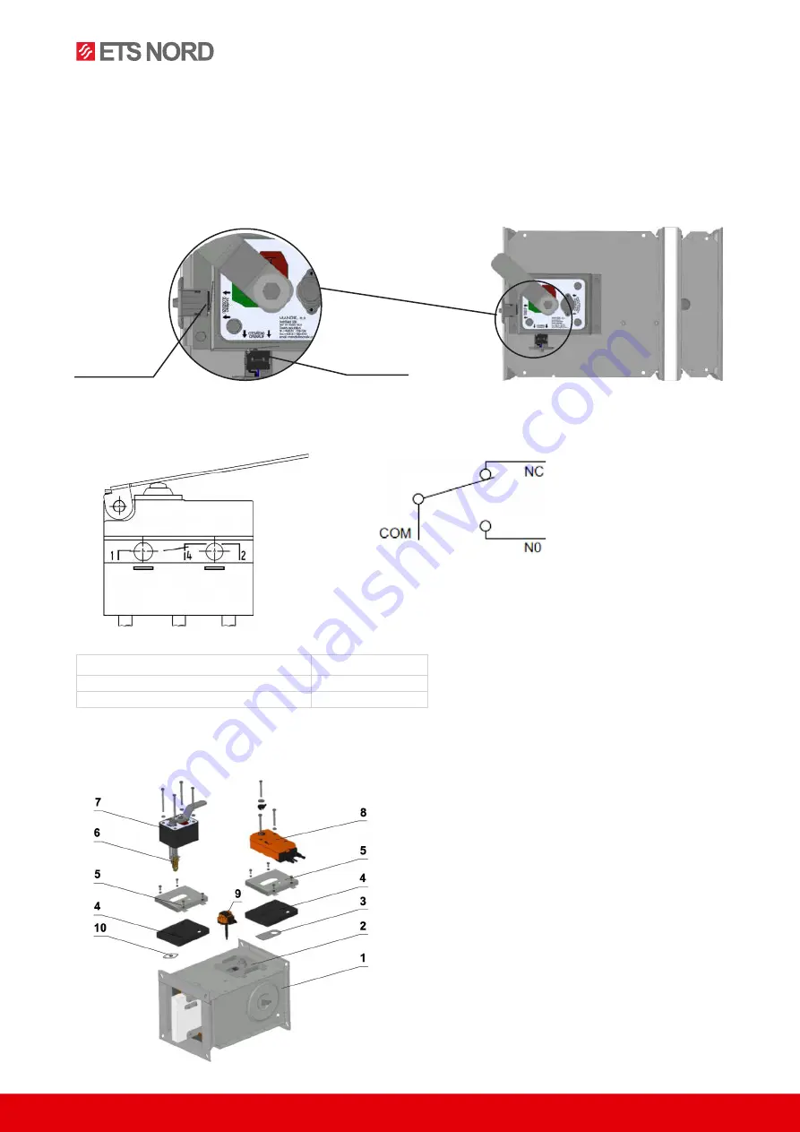
Design .01 with mechanical control can be complemented with a terminal switches signaling of
the damper blade position “CLOSED” and “OPEN”. Limit switches are connected via damper
casing, cables are connected directly to limit switches.
Fig. 5 Design .80
Fig. 6 Limit switch G905-300E03W1
Nominal voltage and maximal current
AC 230 V / 5A
Class of protection
IP 67
Working temperature
–25 °C...+120 °C
Fig. 7 Change of mechanical design for the motorised one or vice versa
Position:
1 Damper
2 Mounting plate
3 Sealing cover
4 Seal plates
5 Mounting plate cover
6 Thermal fuse
7 Mechanics
8 Actuator
9 Temperature sensor
10 Sensor sticker
Limit switch
“OPEN”
Limit switch
“CLOSED”
This limit switch is possible to connect in
following two versions:
a)
CUT-OFF
if the arm is moving … connect wire 1+2
b)
SWITCH-ON
if the arm is moving … connect wire 1+4
1- 1(COM) -
black wire
2- 2(NC) -
gray wire
3- 4(NO) -
blue wire


