ETC Installation Guide
Echo-Echoflex Interface
Echo-Echoflex Interface
Page 3 of 15
ETC
Installation
Install Interface to DIN rail
1:
Ensure the section of DIN rail to be used is mounted
securely according to the manufacturers requirements.
DIN rail is provided by others.
2:
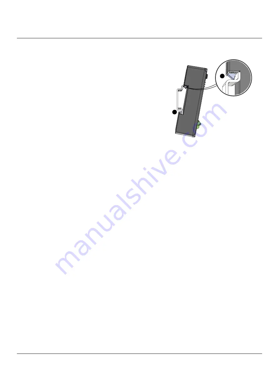
Hook the bottom of the EEI under the lower DIN rail as
shown.
3:
Pivot the device up and depress until the top clip on the
device seats to the top rail.
Connect Wiring
Connect EchoConnect
EchoConnect terminations require Belden 8471 (or equivalent)
between the EchoConnect station bus and Echo-Echoflex Interface, plus one 14 AWG (2.5 mm
2
) ESD
ground wire.
1:
Strip 3/8” (9-10 mm) of insulation from the bare end of the Belden 8471 (or equivalent) wires and
the ESD ground wire.
2:
Loosen the three screw terminals on the EchoConnect terminals.
3:
Insert the data + wire (white is typical) into terminal 3 (identified with a + symbol), insert the data -
wire (black is typical) into terminal 2 (identified with a - symbol), and insert the ground wire (green/
yellow is typical) into terminal 1 (identified with a ground symbol).
4:
Secure the screws firmly onto each wire.
Connect 24 Vdc
An external 24 Vdc (Class 2) power supply is required to power the EEI. Terminate to the interface terminals
labeled 24 Vdc. Terminals accepts 26-14 AWG (0.4 - 1.6 mm
2
) wires (typically a 16 AWG black and red wire
pair).
1:
Strip 3/8” (9-10 mm) of insulation from the bare end of each 16 AWG (1.5 mm
2
) wire.
2:
Loosen the two screw terminals on the 24 Vdc terminals.
3:
Insert the “negative -” wire (black wire typical) into terminal 1 (identified with a - symbol), and insert
the “po” wire (red wire typical) into terminal 2 (identified with a + symbol) of the 24 Vdc
terminals.
4:
Secure the screws firmly onto each wire.
Connect External Antenna (optional)
An external antenna can be used with the EEI.
1:
Connect the EEI antenna to the RF jack.
2:
Move the jumper located below the RF jack to the “Use Ext. Antenna” position.
2
3


