


The difference between the initial value and the modified one is displayed in the delta column.
Press
.
The edging cycle starts.
When the edging cycle is finished, the retouch screen is displayed.
Press
to release the lens.
If necessary, retouch the lens.
Otherwise, start edging the second lens. Select the lens directly on the screen, on the left or right of the
work area.
The edging screen for the second lens is displayed. All finishes chosen and the modifications made
are kept.
9. P
ERFORM
A
P
OLISHING
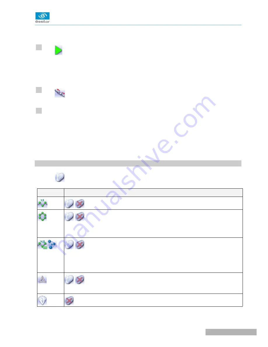
Press the
button to activate/deactivate polishing.
L
ENS
MATERIAL
A
VAILABLE
OPTIONS
The polishing option is pre-selected and is strongly recommended by the manufacturer to
prevent small cracks.
Make sure you select the correct type of material for MHI (> 1.5) or Tribrid lenses and never
polish a lens of this type without water. Otherwise, the polishing wheel could suffer
irreversible damage.
The polishing option is pre-selected.
Not available
>
>
>
>
10
11
12
U
SER
M
ANUAL
> II. E
DGING
A
LENS
65
Pro-E 600 > v1 -02.17
Содержание PRO-E 600
Страница 1: ...User Manual ...
Страница 5: ...I FIRST STEPS WITH PRO E 600 ...
Страница 12: ...II EDGING A LENS ...
Страница 66: ...III CONFIGURING THE EDGER ...
Страница 77: ...IV MAINTENANCE SERVICING ...
Страница 102: ...TECHNICAL DATA ...
Страница 105: ...The back of your machine must be at least 20 cm away from a wall Pro E 600 v1 02 17 110 USER MANUAL TECHNICAL DATA ...
Страница 106: ...GENERAL INFORMATION ...
Страница 110: ...GLOSSARY ...


