Press
to confirm the shelf bevel.
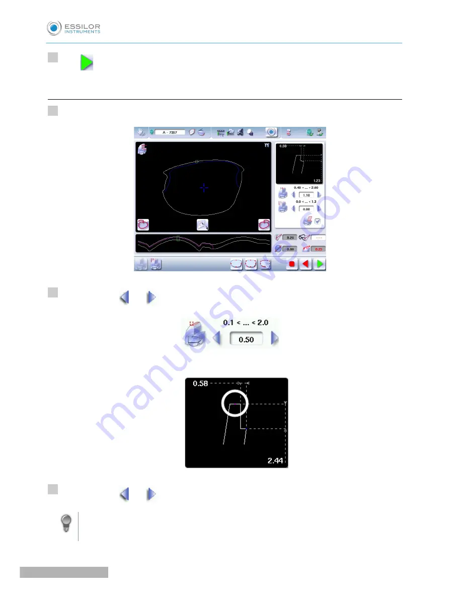
b. Finalize the step bevel settings in “front surface follow-up” mode
Configure the flat side of the bevel and the front shelf bevel of the bevel step.
Press the buttons
and
on the right of your screen to modify the width of the flat side of the bevel.
The result can be viewed in the zoom window.
Press the buttons
and
on the right of your screen to modify the value of front surface tracking.
It is advised to set the value at 0 because front shelf bevel will be viewable on the entire contour
of the shape.
>
7
1
2
3
Pro-E 600_Pro-E 700 > v1 -10.18
94
U
SER
M
ANUAL
> II. E
DGING
A
LENS
Содержание Pro-E 600 edger
Страница 1: ...User Manual...
Страница 2: ......
Страница 6: ......
Страница 8: ......
Страница 9: ...I FIRST STEPS WITH PRO E...
Страница 10: ...Pro E 600_Pro E 700 v1 10 18 10 USER MANUAL I FIRST STEPS WITH PRO E...
Страница 17: ...II EDGING A LENS...
Страница 18: ...Pro E 600_Pro E 700 v1 10 18 18 USER MANUAL II EDGING A LENS...
Страница 127: ...III PREPARING A DRILLED JOB...
Страница 128: ...Pro E 600_Pro E 700 v1 10 18 128 USER MANUAL III PREPARING A DRILLED JOB...
Страница 136: ......
Страница 137: ...IV CONFIGURING THE EDGER...
Страница 138: ...Pro E 600_Pro E 700 v1 10 18 138 USER MANUAL IV CONFIGURING THE EDGER...
Страница 151: ...V MAINTENANCE SERVICING...
Страница 152: ...Pro E 600_Pro E 700 v1 10 18 152 USER MANUAL V MAINTENANCE SERVICING...
Страница 181: ...TECHNICAL DATA...
Страница 182: ...Pro E 600_Pro E 700 v1 10 18 182 USER MANUAL TECHNICAL DATA...
Страница 186: ......
Страница 187: ...GENERAL INFORMATION...
Страница 188: ...Pro E 600_Pro E 700 v1 10 18 188 USER MANUAL GENERAL INFORMATION...
Страница 194: ......
Страница 195: ...GLOSSARY...


