EPSON Stylus Pro 7500
Revision A
Adjustment
Adjustment Steps
201
n
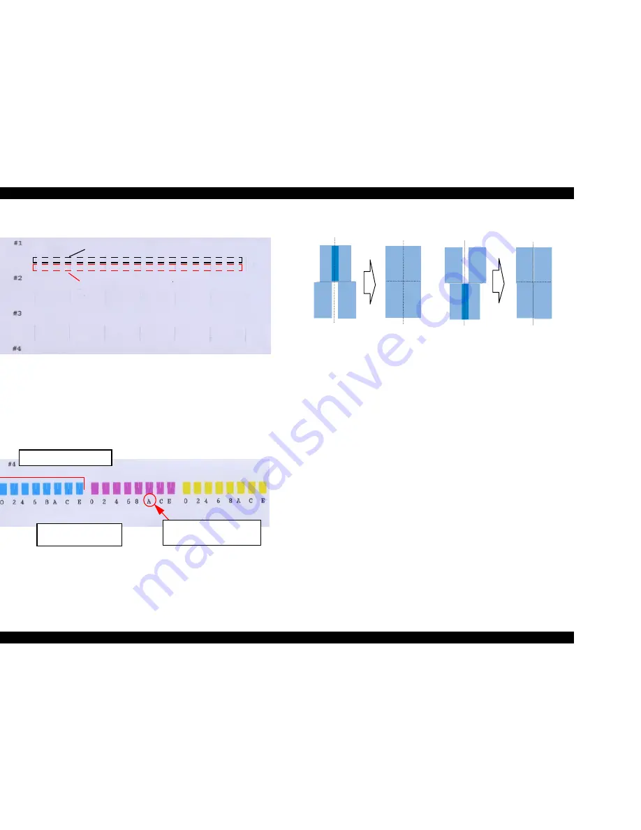
Adjustment Target:There should be no deviation between the lines on the first
pass and the lines on the 2nd pass.
Figure 5-26. Bi-D Adjustment Pattern No. 1 ~ No. 3.
4.
Repeat the above steps 2 and 3 in order to carry out the adjustment of Bi-D printing
patterns No. 1 to No. 3.
5.
Select “ND Base Value Adjust xx” by pressing the Paper Source Button. Check the
results of printing Bi-D adjustment pattern No. 4 and check whether the following
patterns exist in the 8 patterns each of light cyan, light magenta and yellow. The pattern
No. of each pattern is printed in hexadecimal notation beneath it.
Figure 5-27. Bi-D Adjustment Pattern No. 4
n
Each individual pattern consists of 4 rectangular patterns. Search for the pattern
among the 8 patterns in each color where there is no gap and no overlapping
between these 4 rectangles.
Figure 5-28. Bi-D Adjustment Pattern No. 4 Check Method
6.
If you can confirm a pattern among the 8 patterns of each color where there is no gap
and no overlapping between these 4 rectangles, press the Paper Source button and
move to the adjustment menu for each color. Proceed to Step 11.
If you were unable to confirm an appropriate pattern among the 8 patterns printed in
each color, use the Paper Feed + / – buttons to input an estimated value in the “ND
Base Value Adjust xx” menu.
n
Paper Feed + Button:Moves the top 2 out of the 4 patterns within the printed
pattern in a direction so that they separate.
n
Paper Feed – Button:Moves the bottom 2 out of the 4 patterns within the printed
pattern in a direction so that they separate.
Input the estimated values in the “ND Base Value Adjust xx” Menu, then press the
Enter button to print a new Bi-D No. 4 print pattern.
7.
Repeat the above steps 5 and 6 until the the proper printing pattern can be confirmed.
8.
“ND LC: XX” will be displayed in the LCD. In this menu, input the pattern No. of the
pattern among the 8 light cyan printed patterns which was confirmed to be proper using
the Paper Feed + and – buttons. The pattern No. on the printed pattern has the numbers
printed in hexadecimal, with each number incremented by 2 from the number of the
pattern to its left, but in this menu, it is possible to input each of the 16 numbers in
hexadecimal. After inputting a value, press the Enter button.
9.
“ND LM: XX” will be displayed in the LCD. In this menu, input the pattern No. of the
pattern among the 8 light cyan printed patterns which was confirmed to be proper using
the Paper Feed + and – buttons. The pattern No. on the printed pattern has the numbers
Printed lines in the second pass.
Printed lines in the first pass.
One pattern consists of 4
rectangular patterns.
This number printed beneath
each pattern shows the
hexadecimal pattern No.
Patterns for Light Cyan
Содержание Stylus Pro 7500
Страница 1: ...EPSONStylusPRO7500 Color Large Format Inkjet Printer SEIJ00005 SERVICE MANUAL ...
Страница 6: ...Revision Status Revision Issued Date Description Rev A August 31 2000 First Release ...
Страница 10: ...C H A P T E R PRODUCTDESCRIPTION ...
Страница 57: ...C H A P T E R OPERATINGPRINCIPLES ...
Страница 75: ...C H A P T E R TROUBLESHOOTING ...
Страница 95: ...C H A P T E R DISASSEMBLY ASSEMBLY ...
Страница 169: ...C H A P T E R 0 ADJUSTMENT ...
Страница 192: ...PSON Stylus Pro 7500 Revision A djustment Adjustment Steps 192 Figure 5 13 Adjustment Menu ...
Страница 235: ...C H A P T E R MAINTENANCE ...
Страница 241: ...C H A P T E R APPENDIX ...
Страница 258: ...PSON Stylus Pro 7500 Revision A ppendix Exploded View Diagram 258 Figure 7 2 Frame Assembly ...
Страница 259: ...PSON Stylus Pro 7500 Revision A ppendix Exploded View Diagram 259 Figure 7 3 Paper Feed Assembly ...
Страница 260: ...PSON Stylus Pro 7500 Revision A ppendix Exploded View Diagram 260 Figure 7 4 Head Assembly ...
Страница 261: ...PSON Stylus Pro 7500 Revision A ppendix Exploded View Diagram 261 Figure 7 5 Carriage Assembly ...
Страница 262: ...PSON Stylus Pro 7500 Revision A ppendix Exploded View Diagram 262 Figure 7 6 Frame Accessory ...
Страница 263: ...PSON Stylus Pro 7500 Revision A ppendix Exploded View Diagram 263 Figure 7 7 Maintenance Assembly ...
Страница 264: ...PSON Stylus Pro 7500 Revision A ppendix Exploded View Diagram 264 Figure 7 8 Ink Cartridge Holder Assembly ...
Страница 265: ...PSON Stylus Pro 7500 Revision A ppendix Exploded View Diagram 265 Figure 7 9 Cable Guide ...
Страница 266: ...PSON Stylus Pro 7500 Revision A ppendix Exploded View Diagram 266 Figure 7 10 Board Base Assembly ...
Страница 267: ...PSON Stylus Pro 7500 Revision A ppendix Exploded View Diagram 267 Figure 7 11 Cover Assembly ...
Страница 272: ......
Страница 273: ......
Страница 274: ......


