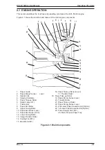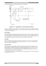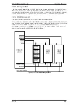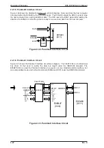
The following figure shows the fuser temperature control operation.
There is a thermistor to the surface of the upper fusing roller to detect its temperature and to
controls the fusing lamp On/Off operation. There are three temperature control modes for the upper
fusing roller on the fusing unit.
Normal Node
When the temperature of the upper fusing roller is less than 100° C (212° F) after printer power on,
fusing temperature is controlled to heat the roller to 195° C (383° F) during standby and to 200° C
(392° F) during printing. After the standby state has continued for 300 seconds or more, or the
printing state has continued for 120 seconds or more, the printer enters hot mode.
Hot Mode
When the temperature of the upper fusing roller is less than 100° C (212° F) or more at the printer
power on, the fusing temperature is controlled keep the roller at 175° C (347° F) during standby
and 200° C (392° F) during printing.
Envelope Mode
When the printer encounters paper smaller than the exective paper, such as an envelope, in the
standard MP tray, the fusing temperature is controlled to keep the roller at 175° C (347° F) during
standby and 200° C (392° F) during printing. When the roller temperature is 100° C (212° F) or
more at printer power on, the fusing temperature is controlled to keep the roller at 175° C (347° F)
during standby and 205° C (401° F) during printing.
The thermostat goes open (S3) if the temperature of the fusing section rises to an abnormally high
level (over 210° C, 410° F).
Temperature
Normal Mode
Hot Mode
Ready
Ready
Print Cycle
(Normal Mode)
Print Cycle
(Hot Mode)
Print Cycle
(Envelope)
Power On
Time
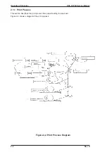
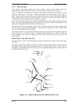
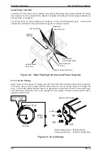
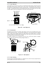
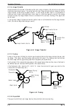
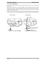
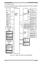
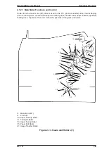
Figure 2-17. Temperature for Fuser Control Procedure
Operating Principles
EPL-N1200 Service Manual
2-12
Rev. A
Содержание EPL-N1200
Страница 1: ...EPSON TERMINAL PRINTER EPL N1200 SERVICE MANUAL EPSON 4006838 ...
Страница 8: ...REVISION SHEET I Revision I Issue Date Revision Page Rev A December 9 1996 1st issue vii ...
Страница 90: ...CN3 Figure 3 5 Connectors on Engine Driver Board Disassembly and Assembly EPL N1200 Service Manual 3 6 Rev A ...
Страница 111: ...Chapter 4 Adjustment No adjustment is required in this product ...
Страница 127: ...6 ii Rev A ...
Страница 133: ...Figure A 2 Engine Section Cable Connection Appendix A EPL N1200 Service Manual A 2 Rev A ...
Страница 147: ...2 CIRCUIT DIAGRAM Figure A 3 C205 MAIN Board Circuit Diagram Appendix A EPL N1200 Service Manual A 16 Rev A ...
Страница 149: ...Figure A 5 C205 Main Board Component Layout Rear Appendix A EPL N1200 Service Manual A 18 Rev A ...

