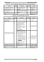
Table 5-7. The LCD Displays Illegal AUX I/F Card or Illegal I/F Module
Cause
Step
Checkpoint
Finding
Solution
The installed I/F card or I/F
module may be illegal. (Check
the user’s guide.)
1
Can this printer use the
inserted I/F card or I/F
module?
No
Replace with a
supported I/F card
or module.
The I/F card or I/F module
may be dead.
2
Does this printer recognize
another, legal I/F card or I/F
module?
Yes
Replace the I/F
card or I/F module.
The C205 MAIN board may be
dead.
3
—
—
Replace the C205
MAIN board.
Table 5-8. The LCD Displays Feed Jam
Cause
Step
Checkpoint
Finding
Solution
Connector for paper take-up
solenoid may be
disconnected.
1
Is connector disconnected?
Yes
Connect it.
The paper take-up solenoid
coil may be open or shorted.
2
Disconnect connector CN6
on the engine controller
board and check coil
resistance between pin 4
and pin 5 on
the disconnected cable side
of the connector using a
multimeter.
Is the resistance
approximately 82 ohms?
No
Replace the paper
take-up solenoid.
If the coil is shorted, check
the solenoid drive circuit
using the procedure below:
1. Set the multimeter for
voltage range.
2. Place the (-) terminal of
the multimeter on pin 7
of connector CN6 on the
engine controller board.
3. Place the (+) terminal of
the multimeter on pin 5
(PICK-UP1).
With power on, does the
multimeter detect any
voltage?
Yes
Replace the paper
take-up solenoid
and the engine
controller board.
Paper take-up sensor flag
position may be incorrect.
3
Is paper take-up sensor flag
position incorrect?
Yes
Reseat the paper
take-up sensor flag.
Paper take-up roller may be
bad.
4
—
—
Replace the paper
take-up roller.
Troubleshooting
EPL-N1200 Service Manual
5-4
Rev. A
Содержание EPL-N1200
Страница 1: ...EPSON TERMINAL PRINTER EPL N1200 SERVICE MANUAL EPSON 4006838 ...
Страница 8: ...REVISION SHEET I Revision I Issue Date Revision Page Rev A December 9 1996 1st issue vii ...
Страница 90: ...CN3 Figure 3 5 Connectors on Engine Driver Board Disassembly and Assembly EPL N1200 Service Manual 3 6 Rev A ...
Страница 111: ...Chapter 4 Adjustment No adjustment is required in this product ...
Страница 127: ...6 ii Rev A ...
Страница 133: ...Figure A 2 Engine Section Cable Connection Appendix A EPL N1200 Service Manual A 2 Rev A ...
Страница 147: ...2 CIRCUIT DIAGRAM Figure A 3 C205 MAIN Board Circuit Diagram Appendix A EPL N1200 Service Manual A 16 Rev A ...
Страница 149: ...Figure A 5 C205 Main Board Component Layout Rear Appendix A EPL N1200 Service Manual A 18 Rev A ...

