3.2.2.15 Thermistor and Thermostat Removal
1.
Remove the fusing unit. (Refer to Section 3.2.2.12.)
2.
Remove the fusing lamp. (Refer to Section 3.2.2.13.)
3.
Take the thermistor cable out of its guide in the fusing unit housing.
4.
Remove two CC (M3
×
6) screws on the top surface of the fusing unit, and remove the side
covers.
5.
Divide the fusing unit into two parts.
6.
Remove one CC (M3
×
10) screw then remove the Thermistor.
7.
Remove two CS(P) (M3x6) screws then remove the thermostat.
CAUTION
* Do not touch the glass surface of the lamp with your bare hands.
* The thermistor and thermostat must be attached at the fusing roller.
* The connector for the thermistor must be inserted firmly.
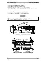
CC(M3X6)
Figure 3-29. Fusing Unit Disassembly
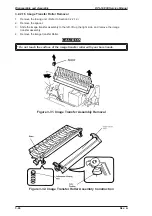
Thermistor
CC(M3X10)
Thermostat
CS(P)(M3X6)
Figure 3-30. Thermistor and Thermostat Removal
EPL-N1200 Service Manual
Disassembly and Assembly
Rev. A
3-23
Содержание EPL-N1200
Страница 1: ...EPSON TERMINAL PRINTER EPL N1200 SERVICE MANUAL EPSON 4006838 ...
Страница 8: ...REVISION SHEET I Revision I Issue Date Revision Page Rev A December 9 1996 1st issue vii ...
Страница 90: ...CN3 Figure 3 5 Connectors on Engine Driver Board Disassembly and Assembly EPL N1200 Service Manual 3 6 Rev A ...
Страница 111: ...Chapter 4 Adjustment No adjustment is required in this product ...
Страница 127: ...6 ii Rev A ...
Страница 133: ...Figure A 2 Engine Section Cable Connection Appendix A EPL N1200 Service Manual A 2 Rev A ...
Страница 147: ...2 CIRCUIT DIAGRAM Figure A 3 C205 MAIN Board Circuit Diagram Appendix A EPL N1200 Service Manual A 16 Rev A ...
Страница 149: ...Figure A 5 C205 Main Board Component Layout Rear Appendix A EPL N1200 Service Manual A 18 Rev A ...

