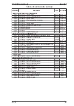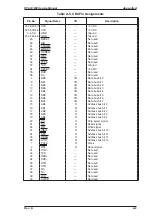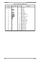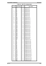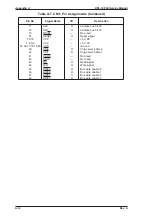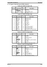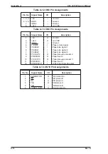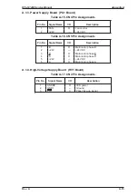
Table A-1. Board Connector Summary
Connector
Description
Pins
Reference
Main Controller Board (C205 MAIN Board)
CN1
Connector for RAM SIMM
72 pins
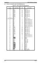
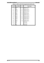
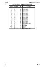
Table A-2
CN2
Connector for engine controller board
50 pins
Table A-3
CN3
Connector for ROM SIMM
72 pins
Table A-4
CN4
Connector for Serial/LocalTalk I/F Module
60 pins
Table A-5
CN5
Not used
—
—
CN6
Connector for RAM SIMM
72 pins
Table A-2
CN7
Connector for optional Type-B I/F card
60 pins
Table A-6
CN8
Parallel-B interface
36 pins
Table 1-8
CN9
Parallel-C interface
36 pins Table 1-8, 9
CN10
Not used
—
—
CN11
Connector for C173 PROG board
80 pins
Table A-7
Engine Controller Board (PWB-A Board)
CN1
Connector for main controller board (C205 MAIN board)
50 pins
Table A-3
CN2
Connector for thermistor of fusing unit
2 pins
—
CN3
Connector for control panel
18 pins
—
CN4
Toner empty sensor
4 pins
Table A-8
CN5
Connector for optical unit
13 pins
Table A-9
CN6
Connector for paper take-up solenoid, paper exit sensor, and
paper empty sensor
8 pins
Table A-10
CN7
Connector for high-voltage supply board
8 pins
Table A-11
CN8
Connector for power supply board
8 pins
Table A-12
CN9
Connector for lower paper cassette
12 pins
Table A-13
CN10
Connector for power supply board
6 pins
Table A-14
Control Panel
CN1
Connector for engine controller board
18 pins
—
Power Supply Board (PU1 Board)
CN1
Connector for AC power inlet
6 pins
—
CN2
Connector for engine controller board
8 pins
Table A-12
CN3
Connector for engine controller board
6 pins
Table A-14
CN4
Connector for cooling fan motor
3 pins
Table A-15
CN5
Connector for main motor
6 pins
Table A-16
CN6
Connector for interlock switch
2 pins
—
CN7
Not used
2 pins
—
High-Voltage Supply Board (HV1 Board)
CN1
Connector for engine controller board
8 pins
Table A-11
CN2
Connector for paper take-up sensor
3 pins
Table A-17
CN3
Connector for PWB-S board
3 pins
—
EPL-N1200 Service Manual
Appendix A
Rev. A
A-3
Содержание EPL-N1200
Страница 1: ...EPSON TERMINAL PRINTER EPL N1200 SERVICE MANUAL EPSON 4006838 ...
Страница 8: ...REVISION SHEET I Revision I Issue Date Revision Page Rev A December 9 1996 1st issue vii ...
Страница 90: ...CN3 Figure 3 5 Connectors on Engine Driver Board Disassembly and Assembly EPL N1200 Service Manual 3 6 Rev A ...
Страница 111: ...Chapter 4 Adjustment No adjustment is required in this product ...
Страница 127: ...6 ii Rev A ...
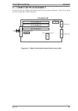
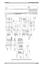
Страница 133: ...Figure A 2 Engine Section Cable Connection Appendix A EPL N1200 Service Manual A 2 Rev A ...
Страница 147: ...2 CIRCUIT DIAGRAM Figure A 3 C205 MAIN Board Circuit Diagram Appendix A EPL N1200 Service Manual A 16 Rev A ...
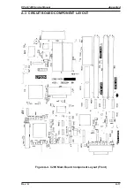
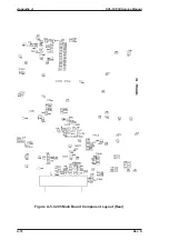
Страница 149: ...Figure A 5 C205 Main Board Component Layout Rear Appendix A EPL N1200 Service Manual A 18 Rev A ...


