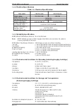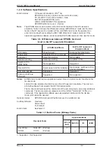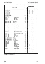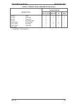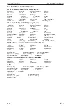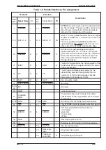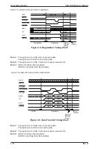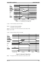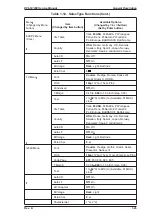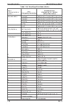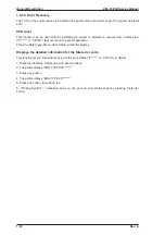
Figure 1-4 shows the parallel interface state switch diagram.
Forward
Data
Transfer
Forward
Idle
STROBE
ACK and BUSY
Compatibility Mode
Terminate
Negotiation
SLCT IN=HIGH
Failed
Negotiation
Reverse
Data
Transfer
Host Busy
Data
Available
Host Busy
Data Not
Available
ERR=HIGH
No data sent
ERR=LOW
Sending data
ERR=LOW
Sending data
ERR=HIGH
AUTO
FEED=LOW
No data sent
Request to
send data
Reverse
Idle
Interrupt
Host
SLCT IN=LOW
ERR=LOW
AUTO
FEED=LOW
AUTO
FEED=HIGH
Figure 1-4. Parallel Interface State Switch Diagram
EPL-N1200 Service Manual
General Description
Rev. A
1-15
Содержание EPL-N1200
Страница 1: ...EPSON TERMINAL PRINTER EPL N1200 SERVICE MANUAL EPSON 4006838 ...
Страница 8: ...REVISION SHEET I Revision I Issue Date Revision Page Rev A December 9 1996 1st issue vii ...
Страница 90: ...CN3 Figure 3 5 Connectors on Engine Driver Board Disassembly and Assembly EPL N1200 Service Manual 3 6 Rev A ...
Страница 111: ...Chapter 4 Adjustment No adjustment is required in this product ...
Страница 127: ...6 ii Rev A ...
Страница 133: ...Figure A 2 Engine Section Cable Connection Appendix A EPL N1200 Service Manual A 2 Rev A ...
Страница 147: ...2 CIRCUIT DIAGRAM Figure A 3 C205 MAIN Board Circuit Diagram Appendix A EPL N1200 Service Manual A 16 Rev A ...
Страница 149: ...Figure A 5 C205 Main Board Component Layout Rear Appendix A EPL N1200 Service Manual A 18 Rev A ...

