


Maintenance 6. Replacing the Reduction Gear Units (Joint #1)
E2C Rev.6
137
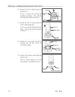
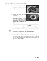
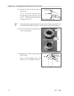
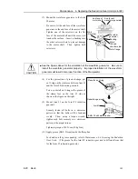
(7) Mount the waveform generator to the Joint
#1 motor.
Be sure to fit the end face of the waveform
generator to the end face of the motor
shaft. Tighten one of the setscrews on the
flat face of the motor shaft until the screw
just touches the surface. Insert a bushing
into the other setscrew hole to prevent
damage to the motor shaft. Then, tighten
both setscrews.
End face of
motor shaft
End face of waveform
generator
Bushing
M4
×
6
(Round
chamfer side)
Waveform generator
M4
×
6
(Flat side)
Flat
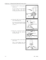
CAUTION
■
See the figures above for the orientation of the waveform generator. Be sure to
install the waveform generator properly. Improper installation of the waveform
generator will result in improper function of the Manipulator.
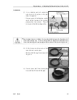
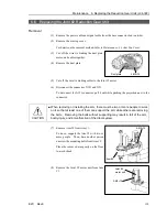
(8) Mount the Joint #1 motor unit on the Joint
#1 reduction gear unit.
Make sure that the motor cables face
toward the round-shaped cut on the
reduction gear flange as shown in the
figure on the right.
Cables
Reduction gear
flange
3-M4
×
10
Round-shaped cut
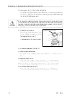
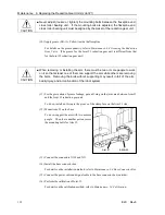
(9) Install the Joint #1 reduction gear unit on
the base.
The round-shaped cut on the reduction gear
flange must be in the position as shown in
the figure on the right.
Reduction gear
flange
Base
8-M4
×
12
Round-shaped cut
Содержание E2C Series
Страница 1: ...SCARA ROBOT E2C series MANIPULATOR MANUAL Rev 6 EM069R1409F ...
Страница 2: ...MANIPULATOR MANUAL E2C series Rev 6 ...
Страница 8: ...vi E2C Rev 6 ...
Страница 14: ......
Страница 81: ...Maintenance This volume contains maintenance procedures with safety precautions for E2C series Manipulators ...
Страница 82: ......
Страница 92: ...Maintenance 2 General Maintenance 80 E2C Rev 6 ...
Страница 118: ...Maintenance 4 Replacing the Cable Unit 106 E2C Rev 6 ...
Страница 194: ...Maintenance 11 Replacing the Signal Relay Board 182 E2C Rev 6 ...


