


Maintenance 5. Replacing the Motors (Joint #1)
E2C Rev.6
111
(6) Install the base connector box.
For details on the installation method, refer to
Maintenance: 3.4 Base Connector
Box
.
(7) Perform the calibration of Joint #1.
For details on the calibration method, refer to
Maintenance: 14. Calibration
.
5.3.2 SM, CM Type Manipulators
Removal
(1) Remove the base connector box.
For details on the removal method, refer to
Maintenance: 3.4 Base Connector Box
.
(2) Disconnect the connectors X110 and X11.
To disconnect the X110 connector, pull it out while pushing the projection next to the
connector.
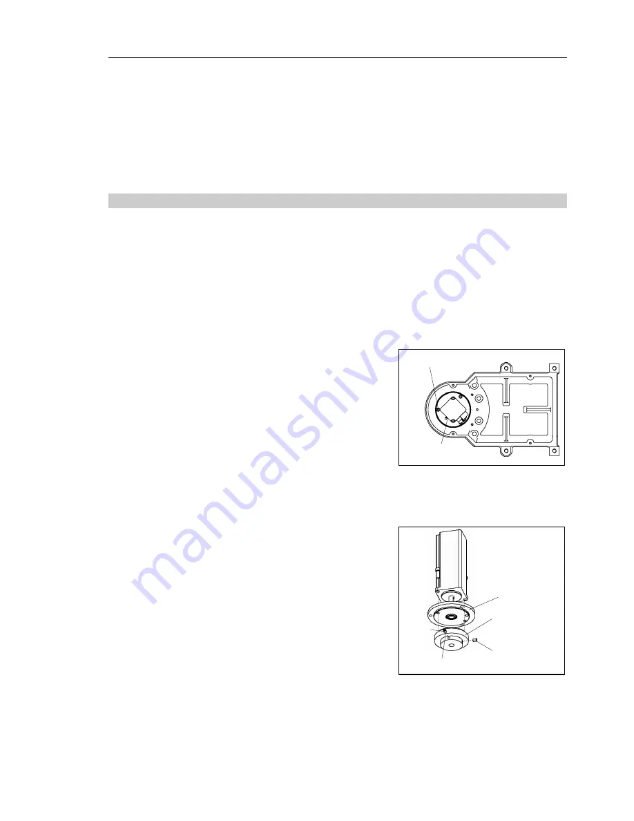
(3) Remove the Joint #1 motor unit from the
base.
To do so, unscrew the bolts from the Joint
#1 motor flange. Then, pull out the motor
straight and upward.
Be careful not to lose the oil seal coated
with black rubber.
If the motor cannot be pulled out easily,
pull it out while moving Arm #1 slowly by
hand.
Motor flange
3-M4
×
15
(4) Remove the waveform generator from the
Joint #1 motor.
There is a brass bushing in one of the
setscrew holes. Be careful not to lose it.
(5) Remove the motor flange from the Joint #1
motor.
Bushing
Waveform
generator
Motor flange
M4
×
6
M4
×
6
)
NOTE
Содержание E2C Series
Страница 1: ...SCARA ROBOT E2C series MANIPULATOR MANUAL Rev 6 EM069R1409F ...
Страница 2: ...MANIPULATOR MANUAL E2C series Rev 6 ...
Страница 8: ...vi E2C Rev 6 ...
Страница 14: ......
Страница 81: ...Maintenance This volume contains maintenance procedures with safety precautions for E2C series Manipulators ...
Страница 82: ......
Страница 92: ...Maintenance 2 General Maintenance 80 E2C Rev 6 ...
Страница 118: ...Maintenance 4 Replacing the Cable Unit 106 E2C Rev 6 ...
Страница 194: ...Maintenance 11 Replacing the Signal Relay Board 182 E2C Rev 6 ...


