EPSON Stylus PHOTO 2100/2200
Revision B
DISASSEMBLY AND ASSEMBLY
Disassembly
166
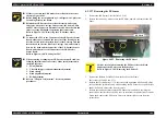
4.2.12.7 Removing the PE Sensor
1.
Remove the Ink System Unit. (Refer to 4.2.10.)
2.
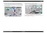
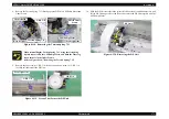
Release the two hooks, which secure the PE Sheet, upward, and remove the PE
Sheet.
Figure 4-102. Removing the PE Sheet
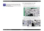
3.
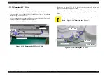
Remove the Release Lever Shaft from the hooks on the Frame.
(Refer to Steps 5 and 6 in 4.2.11.)
4.
Release the Torsion Springs 117.9 that secure the right-hand side Driven Rollers
as seen from the printer rear, and while avoiding the PE Sensor Lever, pull the left-
hand side Drive Rollers to the front to remove.
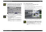
5.
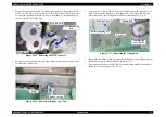
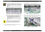
Release the two hooks that secure the PE Sensor Unit, and while avoiding the
projection on the left side of the PE Lever, as seen from the printer front, from the
Frame hook, remove the PE Sensor Unit to the bottom right as seen from the
printer front.
"
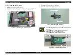
Fit the screws into the CR Encoder Sensor Board in the order
shown in Figure 4-101.
"
Before fitting the screw indicated by 2. in Figure 4-101, place the
Grounding Plate on the Board.
"
Reinstall the CR Encoder Sensor Board securely and evenly.
Otherwise, when the Carriage Unit operates, the Driven Pulley
and PW Sensor Connector will make contact with each other and
there is a strong likelihood of operation fault occurrence.
Refer to Figure 4-101, "Removing the CR Encoder Sensor
Board".
"
To connect the FFC to the Connector of the CR Encoder Sensor
Board, always pass it around the rear side of the Bearing on the
left side (as seen from the printer front) of the Carriage Unit and
into the hook on the rear left of the Carriage Unit, and return it
between the hook and the Connector of the CR Encoder Sensor
Board, and connect it to the Connector of the CR Encoder
Sensor Board.
Refer to Figure 4-100, "Routing the FFC".
A D J U S T M E N T
R E Q U I R E D
"
When removing or changing the CR Encoder Sensor Board, the
following adjustments are necessary. Make the adjustments in
the following order.
1.
PG adjustment
2.
CR tooth skip prevention mechanism adjustment
3.
Head cleanig
4.
Head angular adjustment
5.
Bi-D adjustment
"
Refer to "Chapter 5 Adjustment" for the adjustment
procedures.
C A U T I O N
Fully be careful when removing the PE Sheet since the Hook
Supports of the PE Sheet are easily broken.
Refer to Figure 4-102, "Removing the PE Sheet".
Hooks
PE Sheet
Содержание 2200 - Stylus Photo Color Inkjet Printer
Страница 1: ...EPSONStylusPHOTO2100 2200 Color Inkjet Printer SEIJ01 016 SERVICE MANUAL ...
Страница 8: ...C H A P T E R 1 PRODUCTIONDESCRIPTION ...
Страница 39: ...C H A P T E R 2 OPERATINGPRINCIPLES ...
Страница 69: ...C H A P T E R 3 TROUBLESHOOTING ...
Страница 114: ...EPSON Stylus PHOTO 2100 2200 Revision B TROUBLESHOOTING EEPROM Data Analysis 114 3 4 EEPROM Data Analysis T B D ...
Страница 115: ...C H A P T E R 4 DISASSEMBLYANDASSEMBLY ...
Страница 187: ...C H A P T E R 5 ADJUSTMENT ...
Страница 214: ...C H A P T E R 6 MAINTENANCE ...
Страница 226: ...C H A P T E R 7 APPENDIX ...
Страница 254: ......
Страница 255: ......
Страница 256: ......
Страница 257: ......
Страница 258: ......


