21
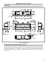
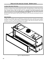
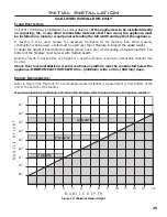
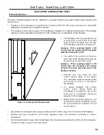
Figure 25: Flame Sensor Coverage
Initial Installation
QUALIFIED INSTALLERS ONLY
i
ntRoDuction
:
This section of the owner’s manual is for the use of qualified technicians only. Fireplace placement,
hearths, facing, mantels, and venting terminations will be covered, as well as the gas and electric systems.
There are several installation safety guidelines that must be adhered to. Please carefully read the safety
precautions at the front of this manual.
• Remove the packaging from the appliance, and check to make sure there is no damage. If damage is
found, please report it to both the carrier and your dealer as soon as possible.
•
Locate a position where the flue system of the stove can be properly installed without damaging the
integrity of the building; e.g. cutting a wall or ceiling joist.
•
Check stove and flue system clearance requirements.
• Locate the stove in a postion so a gas supply line can be run to it.
•
The fireplace may need an electrical connection depending on the options added.
• Locate the stove in a large and open room that is centrally located in the house. This will optimize
heat circulation and comfort.
•
The flow of combustion and ventilation air must not be obstructed.
u
nit
i
nstaLL
p
RepeRation
:
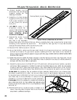
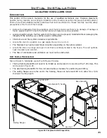
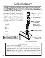
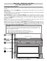
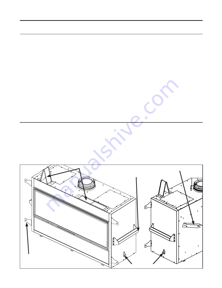
Take a minute to familiarize yourself with Figure 26 below.
•
The top framing standoffs will need to be folded up and secured on one side with a T-20 screw, This
can be seen in Figure 26.
•
The side framing standoffs for this unit also double as handles for positioning and lifting.
•
The nailing flanges secure the unit to the framing, these can be turned 180 to to allow for a 1/2in
shallower framing depth.
Side Standoff / handle
Nailing flanges
Top Standoff
Gas Inlet
Figure 26: Fireplace Install Preperation
Back Standoff
Содержание C72I
Страница 55: ...55 Parts Diagram 1 2 3 4 5 6 9 7 8 12 13 14 10 15 15 ...
Страница 57: ...57 Notes ...
Страница 58: ...58 Notes ...

