11
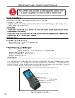
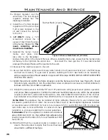
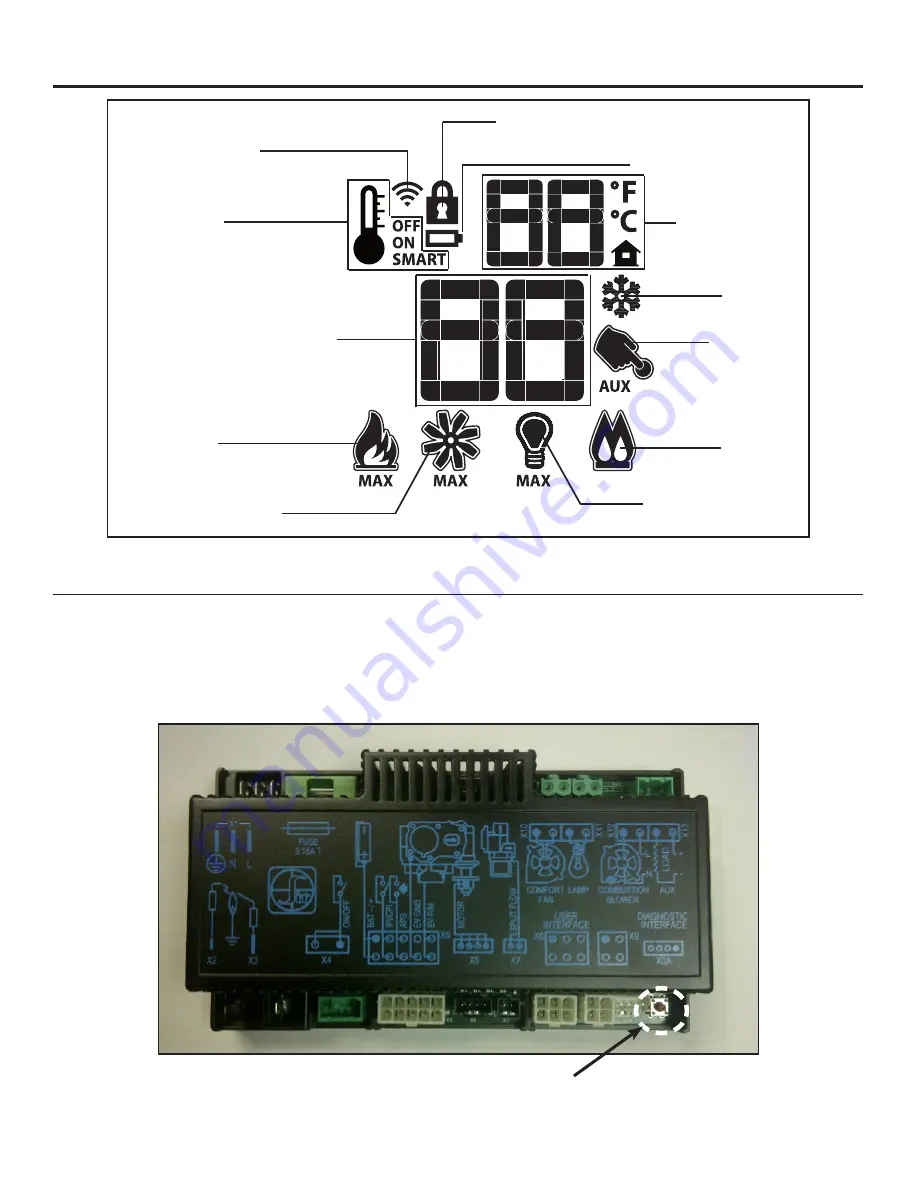
The Proflame 2 IFC (Figure 6) connects directly to the gas valve, stepper motor, pilot, covection fans (optional)
and light kit (optional) with a wiring harness. The IFC is mainly powered by 120 VAC but can also run off a battery
backup four (4) AA type batteries for shorter periods of time. The IFC accepts commands via radio frequency from the
Transmitter to operate the appliance in accordance with the particular Proflame 2 system configuration. The IFC has
a red reset button at the front right corner that is used is to synchronize the Transmitter when using the for the first
time, or after the batteries have been replaced.
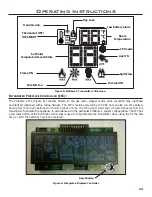
Figure 5: Proflame 2 Transmitter LCD Screen.
Figure 6: Integrated Fireplace Controller
Low battery alarm
Key Lock
Room
Temperature
Dimmer ON
Set Point
Temperature/Level/State
Flame ON
Thermostat OFF/
ON/SMART
Comfort fan
Transmission
Split Flow
Aux ON
CPI mode
Operating Instructions
i
ntegRateD
F
iRepLace
c
ontRoLLeR
(iFc):
Reset Button
Содержание C72I
Страница 55: ...55 Parts Diagram 1 2 3 4 5 6 9 7 8 12 13 14 10 15 15 ...
Страница 57: ...57 Notes ...
Страница 58: ...58 Notes ...


