


Mounting the Switch
2-16 Installation
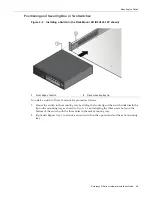
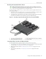
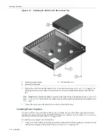
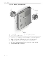
Figure 2-13 Installing the Switch in the D2 Lockbox Tray
2.
Mount
the
switch
inside
the
lockbox
tray
in
the
direction
shown
in
Figure 2
‐
13
on
page 2
‐
16,
aligning
the
three
screw
holes
on
the
bottom
of
the
unit
with
the
three
holes
in
the
lockbox
tray.
3.
Using
the
screws
provided,
fasten
the
switch
to
the
lockbox
tray.
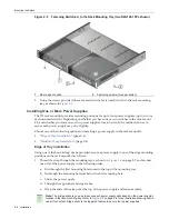
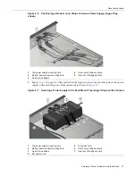
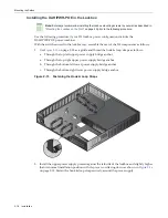
Installing Power Supplies
Once
the
switch
is
secured
in
the
lockbox
tray,
assemble
the
rest
of
the
D2
components
into
the
lockbox.
If
you
are
installing
the
D2
‐
HIPWR
‐
POE
power
combiner
in
the
lockbox,
see
“
Installing
the
D2
‐
HIPWR
‐
POE
in
the
Lockbox
”
on
page 2
‐
18.
To
install
power
supplies
into
the
lockbox:
1.
Using
one
of
the
hook
&
loop
straps
provided,
complete
the
following
steps
to
secure
one
end
of
the
power
supply
in
the
position
shown
in
Figure 2
‐
14
on
page 2
‐
17:
1
Mounting screws (three)
3
D2 switch fan vent
2
Mounting screw holes
Note:
Ensure that the D2 switch is secured to the lockbox tray in the position shown in
Figure 2-21
on page 2-23
. The fan tab on the lockbox tray must face downward when the kit is installed on the
wall.
Содержание D2G124-12
Страница 1: ...Enterasys D Series Ethernet Switch D2G124 12 D2G124 12P Hardware Installation Guide P N 9034395 02 ...
Страница 2: ......
Страница 12: ...x ...
Страница 16: ...xiv ...
Страница 20: ...Getting Help xviii About This Guide ...
Страница 26: ...PoE Power over Ethernet Support 1 6 Introduction ...
Страница 66: ...Resetting the D2 HIPWR POE 3 4 Troubleshooting ...
Страница 74: ...Regulatory Compliance A 8 Specifications ...
Страница 76: ...Index 2 ...


