Completing the Installation
Enterasys D-Series Hardware Installation Guide 2-35
3.
Using
the
four
screws
provided,
attach
the
cover
to
the
switch.
Fasten
securely.
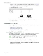
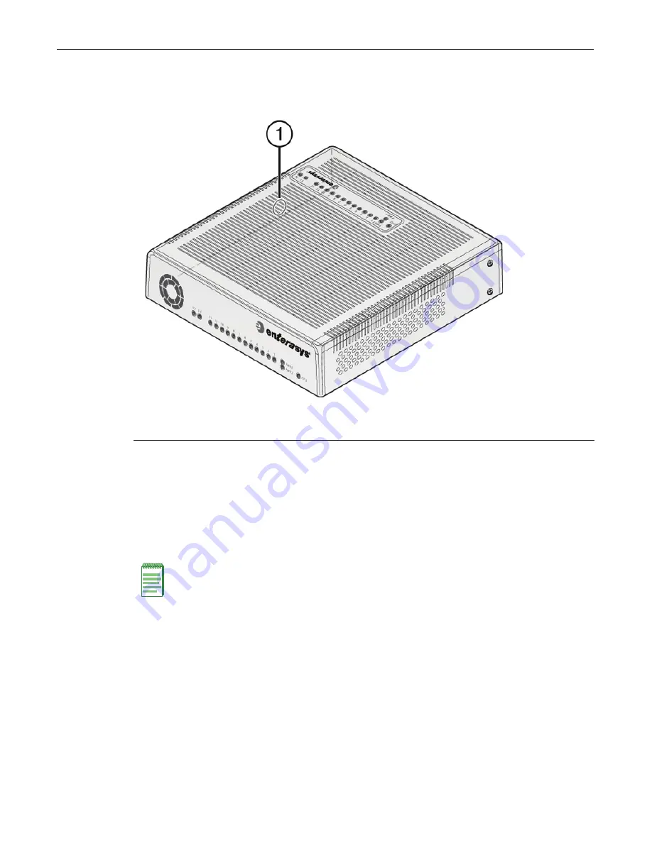
Figure 2-28 Optional Kensington Lock Opening
4.
(Optional)
Secure
the
switch
and
cover
assembly
with
a
Kensington
lock
using
the
optional
knock
‐
out
opening
on
the
cover’s
side
panel,
as
shown
in
Figure 2
‐
28
,
and
the
corresponding
slot
on
the
D2
switch.
Completing the Installation
1.
Power
on
the
switch.
2.
Verify
that
the
PWR1
and
PWR2
power
LEDs
are
lit.
Refer
to
“
Power
LED
Displays
”
on
page 2
‐
27
for
information
on
interpreting
the
power
LEDs.
3.
Verify
that
the
CPU
LED
blinks
initially
then
becomes
solid
green.
4.
Make
sure
that
the
network
devices
connected
to
the
switch
ports
are
powered
on,
then
verify
that
each
Link/Activity
LED
is
ON
(solid
green
or
blinking
green).
5.
At
the
device
connected
to
the
console
port,
perform
the
following:
a.
Enter
admin
for
Username.
b. At
the
Password
prompt,
press
ENTER
(RETURN).
1
Location of knock-out opening for optional Kensington lock
Note:
The D2 fans turn on when power is first supplied to the switch and will shut off automatically.
The fans will turn back on automatically if the temperature ever exceeds the following ambient
thresholds:
• D2G124-12 - 40 degrees C (104 degrees F)
• D2G124-12P - 35 degrees C (95 degrees F)
Содержание D2G124-12
Страница 1: ...Enterasys D Series Ethernet Switch D2G124 12 D2G124 12P Hardware Installation Guide P N 9034395 02 ...
Страница 2: ......
Страница 12: ...x ...
Страница 16: ...xiv ...
Страница 20: ...Getting Help xviii About This Guide ...
Страница 26: ...PoE Power over Ethernet Support 1 6 Introduction ...
Страница 66: ...Resetting the D2 HIPWR POE 3 4 Troubleshooting ...
Страница 74: ...Regulatory Compliance A 8 Specifications ...
Страница 76: ...Index 2 ...


