


Testing Calibration and Relays
Entek IRD 6666 and 6667 Protection Monitors
49
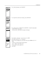
Alarm Relay Test for 6666 and 6667 Monitors
The following steps show you how to test the monitor alarm relays. Most of the relays
reflect the alarm state (Alert or Danger) of an input channel. There is also a System OK
relay that responds to transducer fault, monitor system failure, or loss of power. For the
steps to test the System OK relay, see “Calibration and System OK Relay Test for 6666
Monitor” on page 42 and “Calibration and System OK Relay Test for 6667 Monitor” on
page 45.
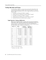
Note: If the LATCHED option is set to YES, you may have to manually reset the relays by
pressing the RES button on the front panel of the monitor. The LATCHED option is on the
ATTRIBS submenu (page 23).
Note: Remember that the RISING option determines whether to activate an alarm on a signal level
rising or falling through the alarm setpoint. See “RISING submenu” on page 25 for more
information. These steps assume you set RISING to YES.
The following relay contacts apply only if you have set STDMAP to YES. If you set
STDMAP to NO or LOGIC, your relay configuration will be different. See “Manual alarm
mapping (STD MAP = NO)” on page 27 or “Logical alarm mapping (STD MAP =
LOGIC)” on page 30 for a description of the other mapping options. Adjust the alarm relay
test steps according to the mapping option you selected for your monitor.
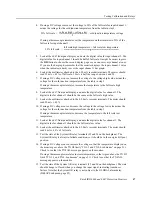
Note: These steps apply to both the 6666 and 6667 monitors. For the 6666, attach a variable
resistance box to the inputs. For the 6667, attach a DC voltage source or thermocouple
simulator.
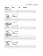
Function
Relay
Terminals (N/C, Comm, N/O)
System OK
and all Alerts
1
25, 26, 27
Channel 1 Danger
2
28, 29, 30
Channel 2 Danger
3
31, 32, 33
Channel 3 Danger
4
34, 35, 36
Channel 4 Danger
5
37, 38, 39
Channel 5 Danger
6
40, 41, 42
Channel 6 Danger
7
43, 44, 45