46
Entek IRD 6666 and 6667 Protection Monitors
Testing Calibration and Relays
Calibration and System OK Relay Test for 6667 Monitor
The following steps show you how to test the calibration for input channel 1 for a 6667
monitor. They also test the function of the System OK relay. To test the calibration for input
channels 2 through 6, substitute the correct input channel terminals.
Note: The input voltage must be corrected by the cold junction temperature voltage.
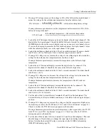
1.
Connect a known DC voltage source (voltage calibrator) to the channel 1 input
terminals on the thermocouple conditioning unit (terminal block). The connection
should be made with normal copper wire. Refer to “Signal Inputs for Testing a 6667
Monitor” on page 43 for details.
You can also use a thermocouple simulator, connecting the wires directly to the channel
1 input terminals.
2.
Connect a multimeter to the 4–20 mA recorder terminals (19 and 20 on the
thermocouple conditioning unit for input channel 1).
3.
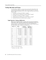
If you are using a DC voltage source, you must correct for the cold junction
temperature. Using a separate thermometer, measure the cold junction temperature at
the thermocouple conditioning unit (terminal block). The following table lists the cold
junction temperature and thermoelectric voltages.
Note:
If using a thermocouple simulator, the thermocouple conditioning unit makes the
temperature correction, so you do not have to measure the cold junction temperature.
Cold Junction
Temperature °C
T/C Type “K”
voltage (mV)
T/C Type “T”
voltage (mV)
T/C Type “J”
voltage (mV)
15
0.597
0.589
0.762
16
0.638
0.629
0.813
17
0.677
0.669
0.865
18
0.718
0.709
0.916
19
0.758
0.749
0.967
20
0.798
0.789
1.019
21
0.838
0.830
1.070
22
0.847
0.870
1.122
23
0.919
0.911
1.174
24
0.960
0.951
1.225
25
1.000
0.992
1.277
26
1.041
1.032
1.329
27
1.081
1.073
1.381
28
1.122
1.114
1.432
29
1.162
1.155
1.484
30
1.203
1.196
1.536

