26
Entek IRD 6666 and 6667 Protection Monitors
Configuration
Understanding Alarm and Relay Mapping
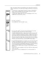
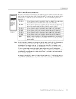
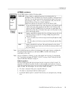
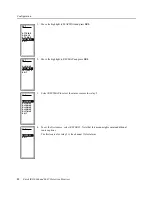
The 6666 and 6667 allow you to choose how the monitor assigns alarms to relays. The STD
MAP option (“RELAYS submenu” on page 22) determines how Alert and Danger alarms
are mapped to alarm relays. System Fail, transducer fail, and loss of power all trip Relay 1.
You can choose the following options for STD MAP:
z
Standard mapping (STD MAP=YES) - All Alert alarms map to Relay 1. Danger
alarms on channels 1 through 6 map to the 2nd through 7th relays, respectively.
Standard mapping uses global failsafe conditions set on the ATTRIBS submenu (page
23).
z
Manual mapping (STD MAP=NO) - You can map each Alert and Danger to one or
more relays. You can also map multiple Alert or Danger alarms to a single relay.
Manual mapping uses global failsafe conditions set on the ATTRIBS submenu (page
23).
z
Logical mapping (STD MAP=LOGIC) - You can map logical combinations of alarm
conditions to individual relays. An alarm condition is a logical combination of Alert
and Danger alarms. Logical mapping allows you to set failsafe conditions for each relay
(relays 2–7) as described in “Setting the failsafe option for individual channels” on
page 39. Relay 1 is always in failsafe condition.
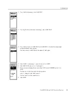
The STD MAP option also controls the other mapping options that appear on the RELAYS
submenu:
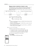
Note: If you change to STD MAP=NO, exit to the previous menu before continuing with settings.
This allows the monitor to change the settings and menu items.
DELAYS
STD MAP
EXIT
ATTRIBS
SET
DELAYS
STD MAP
MAP 1-3
MAP 4-6
EXIT
ATTRIBS
SET
STD MAP = LOGIC
STD MAP = NO
STD MAP = YES
DELAYS
STD MAP
MAPPING
EXIT
ATTRIBS
SET


