28
Entek IRD 6666 and 6667 Protection Monitors
Configuration
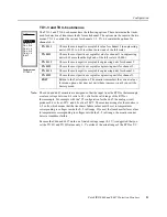
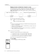
The following table gives an example of alarm mapping for STD MAP=NO.
This mapping means that:
z
Relay 2 changes state when either channel 1 or channel 2 go into Alert alarm.
z
Relay 3 changes state when either channel 1 or channel 2 go into Danger alarm.
z
Relay 4 changes state only if channel 2 goes into Alert alarm.
z
Relay 5 changes state only if channel 2 goes into Danger alarm.
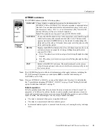
The following is an example of manual mapping. This example shows how to map the
channel 1 Alert alarm to relay 2. It also shows how to remove a relay mapping.
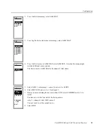
1.
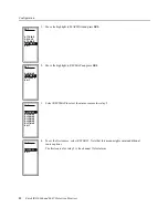
From the Factory menu, move the highlight to RELAYS and press SEL. Use the Up
Arrow or Down Arrow button to move the highlight to MAP 1-3. Press SEL.
2.
The MAP 1-3 submenu appears. The options on this submenu allow you to choose the
relays for the Alert and Danger alarms for channels 1–3. With MAP AL1 selected,
press SEL to choose the relays for the channel 1 Alert alarm.
Alarm
Mapped to
Alert 1
Relay 2
Danger 1
Relay 3
Alert 2
Relay 2, Relay 4
Danger 2
Relay 3, Relay 5
ATTRIBS
DELAYS
STD MAP
MAP 4-6
MAP 4-6
EXIT
MAP 1-3
SET
MAP DG1
MAP AL2
MAP DG2
MAP AL3
MAP DG3
EXIT
SET
MAP AL1


