Safety
Information
Introduction
Product
Information
System
configuration
Mechanical
Installation
Electrical
Installation
Getting
Started
Basic
parameters
Running
the motor
Optimization
SMARTCARD
operation
Onboard
PLC
Advanced
parameters
Technical
Data
Diagnostics
UL Listing
Information
Unidrive SPM User Guide
31
Issue Number: 3 www.controltechniques.com
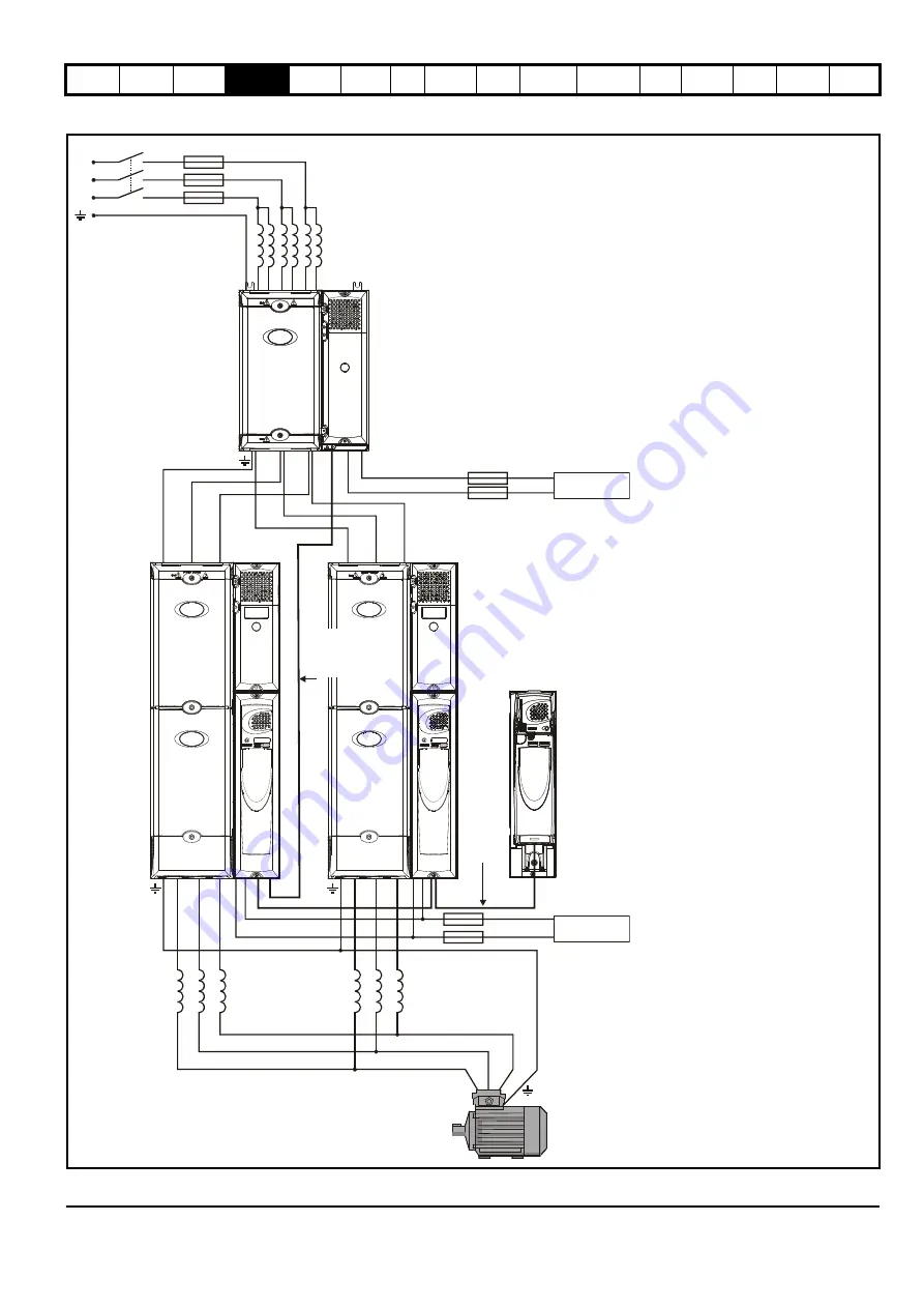
Figure 4-7 Layout for two Unidrive SPMD slave modules with a dual SPMC rectifier operating on a 3-phase AC supply with a remote
mounted control master pod
Slave
OTLXXX
Sharing
chokes
OTLXXX
Sharing
chokes
U
V W
U
V W
+DC -DC
Master/
slave
interface
lead
Rectifier
to inverter
control
wiring
Fuses***
Fuses***
L3
L2
L1
Fuses*
INLX1X
Line reactor**
24Vdc****
24Vdc****
Slave
*Refer to Table 6-16, Table 6-17 on
page 74 and Table 6-18 on page 75 for
technical data and part numbers.
**Refer to Table 6-2, Table 6-3, Table 6-4
and Table 6-5 on page 68 for technical
data and part numbers.
***Fuses are needed only if the power
supply has a current rating of more than
10A.
****Refer to section 14.1.3
Supply
requirements
on page 267 for supply
requirements.
Current sharing between drives
whose motor outputs are
connected in parallel
When used from a 3 phase supply, it is
preferable not to link the DC bus because
the impedance between DC and each
inverter output is just the impedance of
the output chokes. Also, on the input side,
input current sharing is determined only
by making the temperature of the two
rectifiers similar and by ensuring that both
rectifiers see the same impedance to the
line power supply.
To use the remote mounted control
master pod, all modules in the system
must be slaves. This acts as a master
control unit and connects to the system as
shown.
The remote mounted control master pod
allows the user to place all control circuitry
in one low voltage cabinet and permits up
to a maximum of 10 Unidrive SPMD
modules to be connected in parallel.


