background image

49

Reference Manual 

00809-0100-4570, Rev DA

Operation

November 2017

Operation

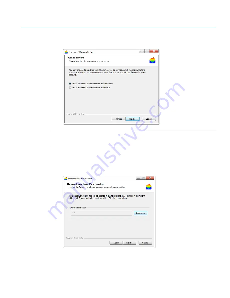
c. If 

Server app files

 check-box was previously checked, select the installation method for the 

Rosemount 3DVision Server. The Server can be installed either as an 

Application

 (Process) or as a 

Service

.

Note

When installing the Server as a Service, the server starts automatically when the OS starts and does not 
require the user to log in.

d. Select 

Next 

to choose the installation folder. 

OR
Select 

Back

 to return to the previous step or

 Cancel

 to stop the installation.

e. To change the default installation folder (if required), select 

Browse

 and specify the desired 

location for the installation.

Содержание Rosemount 5708

Страница 1: ...Reference Manual 00809 0100 4570 Rev DA November 2017 Rosemount 5708 3D Solids Scanner ...

Страница 2: ...ii Section Title November 2017 Reference Manual 00809 0100 4570 Rev DA ...

Страница 3: ...l Installation 3 1 Installation procedure 7 3 2 Mounting considerations 7 3 2 1 Location and positioning guidelines 8 3 2 2 Rosemount 5708 orientation 8 3 2 3 Mounting location 12 3 2 4 Site preparations 13 3 2 5 Site and installation information 14 3 3 Physical mounting 17 5Section 4 Electrical Installation 4 1 Grounding 23 4 2 Cable selection 23 4 3 Hazardous areas 23 4 4 Wiring 24 4 5 Different...

Страница 4: ...rview 41 7 1 1 Server client architecture 42 7 1 2 Multi client 42 7 1 3 System requirements 44 7 1 4 Network considerations 44 7 2 Installing the Rosemount 3DVision software 45 7 2 1 Required information 45 7 2 2 Installation 45 7 2 3 Starting Rosemount 3DVision Server and Client 51 7 3 First time running 54 7 3 1 Creating a new project 54 7 3 2 Vessel configuration 58 7 3 3 Advanced parameters 6...

Страница 5: ...server connection 130 7 5 16Upgrading to Rosemount 3DMultiVision 132 7 5 17Center of Gravity 133 7 5 18Level by Section Output 134 9Section 8 Configuration Rosemount 5708 in a System 8 1 System overview and components 137 8 2 Rosemount System Controller advantages 139 8 3 System requirements 140 8 4 Mounting the Rosemount System Controller 141 8 5 Advanced commissioning steps 142 10Section 9 Servi...

Страница 6: ... 1 Initial settings 159 B 2 Registers 160 B 3 Communication examples 160 CAppendix C Connection via RS 485 C 1 Physical layer 161 C 2 Parameters and units 161 DAppendix D Rosemount LinkPro Operating Instructions D 1 About this document 165 D 1 1 Intended audience 165 D 1 2 Safety 165 D 2 Rosemount LinkPro overview 166 D 2 1 Components 166 D 2 2 Area of application 167 D 2 3 Technical concept 167 D...

Страница 7: ...st performance 175 D 6 3 Configure APN details 177 D 6 4 Configure mode of operation 177 D 7 Troubleshooting 178 EAppendix E Accessories E 0 1 Cable extender 181 E 0 2 Neck Extension 182 E 0 3 Package components 183 E 1 Neck extension 184 E 1 1 Required equipment 184 E 1 2 Assembling the neck extension 184 E 2 Angle adapter 186 E 2 1 Parts of the adapter 186 E 2 2 Assembling the angle adapter 187 ...

Страница 8: ...vi Reference Manual 00809 0100 4570 Rev DA Contents November 2017 Contents ...

Страница 9: ...y understand the contents before installing using or maintaining this product Within the United States Emerson has two toll free assistance numbers Customer Central 1 800 999 9307 7 00 a m to 7 00 p m CST Technical support quoting and order related questions North American Response Center Equipment service needs 1 800 654 7768 24 hours includes Canada For equipment service or support needs outside...

Страница 10: ...y continued use of product that has been damaged or modified without prior written authorization is at the customer s sole risk and expense Explosions could result in death or serious injury Verify that the operating environment of the transmitter is consistent with the appropriate hazardous locations specifications To prevent ignition of flammable or combustible atmospheres disconnect power befor...

Страница 11: ...on regulations 1 2 Storage and transport The Rosemount 5708 is protected by special packaging during transport and is guaranteed to handle normal loads during transport Indication of a potentially dangerous situation which could result in serious injury to persons and or damage to the Rosemount 5708 Procedures and instructions in this manual may require special precautions to ensure the safety of ...

Страница 12: ...2 Reference Manual 00809 0100 4570 Rev DA Introduction November 2017 Introduction ...

Страница 13: ...and volume of the stored contents and can generate a 3D visualization position and form of the material within the container for displaying on remote computer screens 2 2 Applications 2 2 1 Wide application range The Rosemount 5708 can measure practically any kind of solid material stored in a variety of containers including large open bins bulk solid storage rooms stockpiles and warehouses mappin...

Страница 14: ...e It is appropriate for vessels of up to 40 ft ft 12 m in diameter and at least twice as high open bins and stockpiles It presents the minimum and maximum Level Distance measurements along with the calculated average and volume Rosemount 5708S The Rosemount 5708S models have the capability of generating a 3D visualization of the stored contents on a remote computer and to be mounted with additiona...

Страница 15: ...n Three antennas sealed with a customized tin foil 2 04 in 52 mm thread to fasten the Rosemount 5708 to a mounting plate and a fastening nut Temperature sensor Sealing rubber O ring Orientation indications The head contains The electronic board One gland and one blind gland Grounding screw Fastening screw to the transducers ...

Страница 16: ...6 Reference Manual 00809 0100 4570 Rev DA Rosemount 5708 Overview November 2017 Rosemount 5708 Overview ...

Страница 17: ...semount 5708 connected to the PLC Power up the Rosemount 5708 and check polling address Set polling address In daisy chain connection make sure that each Rosemount 5708 has a different polling address and one of the Rosemount 5708 is set with polling address of 00 In case of daisy chain connection write the polling addresses on the vessel drawings for all Rosemount 5708 Verify every Rosemount 5708...

Страница 18: ...e usage verify that the sealing material is resistant to the stored medium The maximum allowed pressure is indicated on the type label of the sensor Installation location Choosing the proper installation location for the unit is an important part of the installation process The wrong mounting location may result in erroneous measurements or loss of performance The following factors must be taken i...

Страница 19: ...on Figure 3 1 Mounting Direction 0 Indication toward Vessel Center Figure 3 2 The 0 Indication Standpipe mounting When mounting using a standpipe it should be assembled and positioned at a height that leaves at least 0 4 in 10 mm below the standpipe for the antenna end protrudes as shown in Figure 3 3 ...

Страница 20: ...stic beam transmitted and received as shown in Figure 3 4 Figure 3 4 Avoid Interference with the Acoustic Beam Inflowing material Do not mount the Rosemount 5708 in or above the filling stream or close to the stream or in the filling stream The Rosemount 5708 should be located with a clear line of sight to the top of the material at high levels where it will not be affected by the filling stream o...

Страница 21: ...ng the installation location consider the filling and emptying points and maintain at least 24 in 600 mm from the filling point Fitting The fitting area should be prepared to ensure the antennas are positioned perpendicular to the ground as shown in Figure 3 6 Figure 3 6 Keep the Antennas in Vertical Position to the Ground Minimum 24 in 600 mm 90 ...

Страница 22: ...l Installation November 2017 Mechanical Installation 3 2 3 Mounting location Mount Rosemount 5708 perpendicular to the ground Keep necessary distance from side wall Keep necessary distance from filling points 90 Minimum 24 in 600 mm Minimum 24 in 600 mm ...

Страница 23: ...n the Rosemount 5708 at a height that leaves at least 0 4 in 10 mm below the standpipe for the antenna end to protrude 3 2 4 Site preparations Prior to installation complete and verify the site preparations described in this section For optimal installation ensure the Rosemount 5708 can be positioned and fitted according to the guidelines in Mounting location on page 12 Minimum 0 4 in 10 mm for st...

Страница 24: ...a 24 Vdc power supply near the Rosemount 5708 mounting location Make sure that you use proper cables for wiring The Rosemount 5708 is a 4 wire device The voltage supply and data output 4 20 mA are carried along two separate two wire connection cables Communications For RS 485 communication use shielded twisted pair cables with 120 Ω impedance Make sure the cables are approved for RS 485 communicat...

Страница 25: ...indrical Rectangular Top shape Flat Flat Cone Pyramid Top diameter A ______ Height B ______ Height A ______ X ______ Y ______ Dome Height A ______ Center shape Cylinder Cube Diameter A ______ Height B ______ Height A ______ X ______ Y ______ Bottom shape Flat Flat Cone Cone Height A ______ Bottom diameter B ______ Height A ______ Bottom diameter B ______ Pyramid Pyramid Height A ______ X ______ Y ...

Страница 26: ...ation of every device must be specified When the application has more than a single filling point all other filling points must be specified as well Internal structure like Ladder pipe window screw door rail support beam or any other obstacle which is visible to the 5708 scanner Drawings should be available Internal movement YES NO If yes please describe X Y Offset from roof 1st Rosemount 5708 loc...

Страница 27: ...d Empty Calibration in Rectangular and Cylindrical Vessels Application process 3 3 Physical mounting Step 1 Check power and cables 1 Check the 24 Vdc with a voltmeter 2 Check the resistance of the data communication lines 3 Verify 60 Ω of resistance when connecting the 120 Ω resistors at both ends Full calibration ft m Empty calibration ft m Maximum filling rate lbs hour tons hour Maximum emptying...

Страница 28: ...vember 2017 Mechanical Installation Step 2 Install the mounting plate 1 Verify the O rings on the neck tube are in place 2 Remove the nut from the neck tube 3 Place the mounting plate over the neck tube Note Make sure the hole diameter D in the center is 2 05 in 52 mm D ...

Страница 29: ...g plate 5 Lower the antenna and mounting plate into the fitting location on the silo 6 Bolt the mounting plate onto the flange of the silo Step 3 Rotate antenna toward silo center 1 Slightly loosen the nut that connects the antenna with the mounting plate 2 Rotate the antenna The notch on the top of the thread must be directed toward the center of the silo 3 Tighten nut ...

Страница 30: ...809 0100 4570 Rev DA Mechanical Installation November 2017 Mechanical Installation Step 4 Install head 1 Remove the rear panel A Hex key 4 mm 2 Remove the cable clamp 3 Verify the presence of the O ring on the tube neck 4x A ...

Страница 31: ...nsert the Rosemount 5708 head onto the neck tube a Rotate the Rosemount 5708 head to the desired direction The head may be installed in six different positions To avoid direction confusion we can recommend to install the head in the same direction as the antennas b Make sure to push the head all the way down until it fully contacts the top of the neck tube A A Antenna cable ...

Страница 32: ...nical Installation November 2017 Mechanical Installation 6 Tighten the front screw 7 Re mount the cable clamp 8 Gently connect the antenna cable connector Make sure the latch is clicked and locking the connector A B A Hex key 4 mm B Open wrench 13 mm ...

Страница 33: ...for RS 485 communications For 4 20 mA communication use a low resistance cable and make sure the cables are rated for analog signals For daisy chaining a single 4 wire cable can be used both for RS 485 and the 24 Vdc power supply Make sure only to use a proper cable gaging AWG Use 8 13 mm 20 24 AWG diameter cables to ensure proper and effective sealing of the cable gland entry opening Select a cab...

Страница 34: ... on power supply specifications refer to Rosemount 5708 Product Data Sheet 4 20 mA 4 wire The power supply and signal current inputs must be carried over two separated pairs Connection procedure For detailed information on the connection procedure see Different connection methods on page 29 Note Use direct connection between the Rosemount 5708 and the plant PLC SCADA For a remote connection use th...

Страница 35: ...connected 2 Loosen the compression nut of the cable gland entry 3 Insert the cable through the cable gland entry Always observe the following safety instructions Connections must be made only in the complete absence of line voltage If over voltage is expected overvoltage arresters should be installed Use only a safety certified power supply with dual insulation between the primary and output for p...

Страница 36: ... avoid a loose connection and or operational problems 6 Connect the cable wires according to the wiring diagram See Different connection methods on page 29 for different connection methods Note When connecting the last Rosemount 5708 in the chain a 120 Ohm resistor must be connected as well See Figure 4 6 on page 31 In any installation of the 5708 whether it is a single unit on a silo or multiple ...

Страница 37: ...n terminals C RS 485 Modbus RTU communication terminals 7 Connect the external ground terminal The Rosemount 5708 must be grounded electrostatically For internal grounding use the power cable ground For external grounding use the earth potential equalization of the plant Note An internal cable grounding connection is also possible using the inner connection as shown below C B A ...

Страница 38: ...stallation November 2017 Electrical Installation Figure 4 2 Grounds Screws A Internal ground screw B External ground screw 8 Tighten the compression nut over the cable gland entry opening 9 Attach the rear panel back to position and tighten the screws A B 4x ...

Страница 39: ...ck as shown in Figure 4 3 Ports 3 and 4 are the negative and positive poles respectively Figure 4 3 Port 3 and 4 The 4 20mA line is connected directly from the Rosemount 5708 mounted on the vessel to the PLC DCS Display or any other device as shown in Figure 4 4 Figure 4 4 Rosemount 5708 Connected to PLC A Active B 4 20 mA C Passive D PLC Controller Note The maximum cable length of a 4 20 mA cable...

Страница 40: ...an appropriate cable rated for RS 485 the cable should be of twisted pair have 120 Ω impedance and shielded The total length of the cable should not reach 3280 ft 1000 m If multiple units of Rosemount 5708 is connected together all devices must be connected in parallel mode in the RS 485 ports Hence all the positive ports of the RS 485 should commonly be connected and all the negative ports of the...

Страница 41: ... to the Appendix D Rosemount LinkPro Operating Instructions Note In such communication mode only one computer running the Rosemount 3DVision software can be connected to the Rosemount 5708 4 5 4 TCP IP communication The RS 485 bus can be converted to TCP IP communication TCP IP to RS 485 converter installation should be done as with any Rosemount 5708 including the resistors and daisy chain consid...

Страница 42: ...32 Reference Manual 00809 0100 4570 Rev DA Electrical Installation November 2017 Electrical Installation ...

Страница 43: ...re the Rosemount 5708L by using the Rosemount 3DVision software Figure 5 1 User Interface 1 Connect power to the Rosemount 5708 and open the front cover The Rosemount 5708 initializes a self test for about 30 seconds The display remains blank during this time Navigates back within a function menu Continuous 3 second press exits to the default screen Navigates upwards in the navigation list Navigat...

Страница 44: ... the startup process is complete the following screen appears showing the current average distance measurement The top line displays the Rosemount 5708 tag name By default this line is empty Press to enter the main menu 1 From the main screen select the key to enter the main menu 2 In the main menu use the keys to scroll down to Polling Address Select to switch to the Polling Address configuration...

Страница 45: ...e the key to modify the value 5 Select the vessel shape either Cylindrical or Rectangular a Use the keys to switch between the options Select to continue b If Cylindrical is selected set vessel diameter Use the key to switch between the two digits Use the key to modify the value Select to continue c Set Scanner Height from the bottom edge of the vessel to the mounting plate point above the antenna...

Страница 46: ...odify the value Select to continue c Set Scanner Height from the bottom edge of the vessel to the mounting plate point above the antenna Use the key to switch between the two digits Use the key to modify the value Select to continue d Set the distance from the x axis see Figure 3 7 on page 16 Use the key to switch between the two digits Use the key to modify the value Select to continue e Set the ...

Страница 47: ...lue Select to continue 6 Select to keep the default setting Note if using an angle adapter set the angle value Use the key to switch between the two digits Use the key to modify the value Select to continue 7 Set the process rate using the key Select to continue Make sure to always use Regular Process For the Slow and Fast Process options contact your local customer service 8 Set the temperature u...

Страница 48: ...ntinue a If Map False Echoes is selected set the distance from the top of the antenna assembly to the end of the scanning point Always make sure to map false echoes above material level The recommended level is 3 ft 1 m above actual material level Use the key to switch between the two digits Use the key to modify the value Select to continue b Approve or decline the false echo mapping operation Us...

Страница 49: ...ation is completed with the Rosemount 3DVision software For further information see Section 7 Operation Figure 6 1 User Interface 1 Connect power to the Rosemount 5708 and open the front cover A self test will start and run for about 30 seconds The display remains blank during this time Navigates back within a function menu Continuous 3 second press exits to the default screen Navigates upwards in...

Страница 50: ...ain screen 4 When the startup process is complete the following screen appears showing the current average distance measurement The top line displays the tag name By default this line is empty Select to enter the main menu 1 From the main screen select the key to enter the main menu 2 In the main menu use the keys to scroll down to Polling Address Select to switch to the Polling Address configurat...

Страница 51: ...stored in storage vessels The application periodically supplies information providing the essential real time data required for critical decisions necessary for successful plant management Figure 7 1 Rosemount 3DMultiVision Output Example The Rosemount 3DVision works in conjunction with Rosemount 5708 providing measurement data to a Windows based computer running the programs The program continuou...

Страница 52: ...rts collects and stores readings and transfers the information to all connected Rosemount 3DVision clients The server computer should be running and logging at all times The Rosemount 3DVision Client is a graphical and interactive program allowing the user to receive online measurement data view a 3D visualization of the material stored in the vessels add or remove sites vessels and Rosemount 5708...

Страница 53: ... screen In addition each Rosemount 3DVision Server can connect and supply information to an unlimited number of Clients These features enable high flexibility in inventory management and amount of personnel reviewing the information When more than one client is logged as technician only one can perform changes to the vessel or the configuration If for example one user opened the Configuration Wiza...

Страница 54: ...unt 3DVision Server from an external connection WAN Wide Area Network it is required to open TCP Ports in Firewalls Routers or other devices or applications that might block such communication The required TCP Ports are 22220 Control Port 22221 Used for data Connection 22222 Connection of Rosemount 3DVision Client to Server 22223 Logs Download Data Port Additional TCP ports may be required when in...

Страница 55: ...nitial configuration it is recommended to install both Rosemount 3DVision Server and Rosemount 3DVision Client on the same computer However it is possible to install the Rosemount 3DVision Server and Client on separate computers and connect to them accordingly If you are using the Rosemount System Controller unit skip to Starting Rosemount 3DVision Server and Client on page 51 It is recommended to...

Страница 56: ...stalled the Rosemount 3DVision setup wizard automatically detects and prompts you to install this component The installation file of the NET Framework is provided in the flash drive supplied with the software and Rosemount System Controller 3 Select your preferred language and OK to proceed The installer s welcome box appears 4 Select Cancel to stop the installation process and close the window OR...

Страница 57: ...ll available features The setup wizard completes the software installation OR Select Custom install for remote client installations and select Next to change the installation folder and select applications to install 6 Select I do not accept the to cancel and exit the installation OR Select I accept the and select Next to proceed with the installation ...

Страница 58: ...o confirm and proceed to the next step OR Select Back to return to the previous step or select Cancel to stop the installation 9 When the Custom Install option is selected a Check the required options for the applications to be installed You may choose to install Client app files only Server app files only or both Note When installing a remote client install the Client app files only b Select Next...

Страница 59: ...r as an Application Process or as a Service Note When installing the Server as a Service the server starts automatically when the OS starts and does not require the user to log in d Select Next to choose the installation folder OR Select Back to return to the previous step or Cancel to stop the installation e To change the default installation folder if required select Browse and specify the desir...

Страница 60: ...llation 10 Select the Windows Start Menu folder where you want the program s shortcuts to be added in the Choose Start Menu Folder window You can also enter a name to create a new folder 11 Select Install to proceed to install the software Select Back to return to the previous step or Cancel to stop the installation ...

Страница 61: ...ount 3DVision Client for the first time the system asks for details required to establish a connection to the Rosemount 3DVision Server Following a successful connection a new window appears to enter a user name and password The default user level is Administrator with the default user name admin and password admin 1 Double click the Rosemount 3DVision Client icon to start the client application T...

Страница 62: ...running the Rosemount 3DVision Server application c In the Server Port field verify that the server port is set to 22222 d Select OK e Select Stay Signed In to automatically sign in on the next execution of the Rosemount 3DVision Client application f Select Slow Connection to increase timers and timeouts of various commands in case of slow communication between the Rosemount 3DVision Server and th...

Страница 63: ...n to the technician mode of the system enter the technician mode user name and password For further details refer to Switch User on page 74 4 The server application may need some time to initialize communications with the Rosemount 5708 and clients Ensure the server icon appears on the task bar as shown The server should remain running Manually running the server is required only if the computer i...

Страница 64: ...se steps are basic and mandatory for the completion of a vessel commissioning For additional changes and modifications of the vessel and for the Rosemount 3DVision Software refer to the various software menus starting on page 66 7 3 1 Creating a new project Following a successful login the software automatically opens the last project If no project exists create a new project by selecting the New ...

Страница 65: ...nly An upgrade to the Rosemount 3DMultiVision version is required for configuring more than one site Contact your local Emerson representative for purchasing a license key for upgrading to Rosemount 3DMultiVision 5 Enter the site name limited to 16 characters number of vessels in the site and number of Rosemount 5708 in each vessel Sites vessels and Rosemount 5708 can be edited later 6 Select the ...

Страница 66: ...8 units in each vessel connection method and serial COM port Selecting Next switches to the next site Repeat site configurations for each site In the following example a single site is defined Note It is possible to change at any time the communication method switch user to technician select the device from the device selection drop list appear above the 3D visualization see Figure 7 15 on page 63...

Страница 67: ...rresponding vessels are displayed in the vessel selection bar Selecting a vessel from the vessel selection bar displays various types of information and configuration options related to that vessel in the main work area This information is organized in tabs Overview Logs and Parameters Right clicking a vessel icon opens a menu with options related to that vessel Multiple devices may be defined und...

Страница 68: ...d The options are Cylinder or Cube or cylinder sector Set the dimensions For a cylinder shape set the height and the diameter For a cubic shape set the height width and length of the vessel according to the X and Y axis respectively For a cylinder sector set both bottom and top shapes to flat set the internal and external diameters the sector angle from 15 and up to 90 degrees and set the sector h...

Страница 69: ...osition is calculated automatically when the X and Y coordinates modified or there is a change to the offset from the top The angle is being calculated automatically when the X Y coordinates changes When Senior Technician user is logged in there is an option to modify the angle manually by checking the Set device angle manually When entering this step the 3D visualization is showing the silo from ...

Страница 70: ...e vessel Up to nine filling points may be defined Select Add and enter the X and Y coordinates in the Filling Points table and press Enter after every number entered Filling points are marked as an inverted orange cone at the set position Select Delete to remove the selected filling point Select Clear to remove all filling points Figure 7 11 Configuration Wizard Step 3 Device Position 11 Select Ne...

Страница 71: ...f the Rosemount 5708 antenna case Set the Empty Calibration by setting the level or the distance from the top of the vessel to set the 0 4mA see Figure 7 12 Default value is set to the bottom of the vessel Select the Default button to set the full and empty calibration levels to default values Select View Table to open a window showing a summary table of each Rosemount 5708 in the vessel and the a...

Страница 72: ...eed additional changes 7 3 5 False echo mapping Using the Echo Curve Analysis result it is possible to determine if false echo mapping actions are needed For additional information see False Echo Mapping on page 112 7 3 6 Vessel properties configuration The example below shows how to configure a single site with a single vessel and two Rosemount 5708S Note In order to configure a vessel with more ...

Страница 73: ...t appears see Figure 7 15 Select the required device for configuration from the list Figure 7 15 Rosemount 3DMultiVision Vessel Overview Tab 5 Select the Parameters tab to configure the Rosemount 5708 parameters Figure 7 16 on page 64 Note Rosemount 5708 parameters can be modified only in technician mode For further information on the connection methods refer to Communication methods on page 91 ...

Страница 74: ...ort and polling address Figure 7 17 Rosemount 3DMultiVision Vessel Devices Tab 7 Set Connection Type the unsupported types are visible but not selectable Note Connection type is enabled for editing only when the Rosemount 5708 is disconnected For further information on the connection methods refer to Communication methods on page 91 8 Set Serial COM Port 9 Set Polling Addresses ...

Страница 75: ...ction is established select the site from the site selection bar as shown to the right The vessel profile screen appears with the results of the scanned measurements 13 To view a 3 dimensional profile right click on a vessel in the main work area and select Show 3D visualization from the drop down menu The profile window opens Figure 7 18 Figure 7 18 Product 3 Dimensional Profile Note When connect...

Страница 76: ...the main menus File Communication Edit Device View Tools and Help B Project toolbar Includes various tools for project management and operations including project opening and saving connection to sites and data loading C Site selection bar A project allows multi site management where each site may include multiple vessels In the site selection bar a site can be selected for monitoring and operatio...

Страница 77: ...and Software upgrades and then uploading the modified projects back to the server Option Description New Starts a new empty project Open Opens an existing project Save Project Saves the current project Save Project As Saves current project as a different name Export Project from Server Exports a project in XML format Import Project to Server Imports a project in XML format Delete Project Deletes a...

Страница 78: ...cted it displays Rosemount 5708 related commands e g Connect Disconnect The following options are available when a vessel is selected Figure 7 22 Communication Menu Table 7 2 Communication Menu Option Description Connect All Connect to all the devices in the selected site Disconnect All Disconnect from all the devices in the selected site Load from Vessels Download all data from all vessels Connec...

Страница 79: ... graphic figures Additional option only available when a vessel is selected Add text labels on the 3D visualization X Y and Z coordinates are referenced to the center axis located at the bottom center of the vessel Edit Project An interface option to rearrange the vessels and sites per requirements Save Selected Vessel Configuration As This operation saves the selected vessel configuration into an...

Страница 80: ...eference Manual 00809 0100 4570 Rev DA Operation November 2017 Operation Figure 7 24 Edit Project Option Figure 7 25 Vessel Graphic Figures Figure 7 26 Example of Adding a Text Label to the 3D visualization ...

Страница 81: ...on about all functions under the Output Settings window refer to Device output settings on page 103 Echo Curve Analysis Ctrl Z For complete information about all functions under the Output Settings window refer to Echo Curve Analysis on page 109 Echo Curve Analyze Viewer Ctrl V For complete information about all functions under the Output Settings window refer to Viewing Echo Curve Analysis on pag...

Страница 82: ...l Note To open and view report files in Excel format Microsoft Excel must be installed on the computer Reports Definition Wizard F9 Opens a wizard to set edit and generate reports Reports Wizard on page 116 Export Present Project Reports from Server Opens a date picker to select the From and To dates for the project reports Select OK to retrieve the list of corresponding report files from the serv...

Страница 83: ... the server computer See Figure 7 32 Scada Configuration Allows SCADA systems to be integrated to the server Opens a window for activating integration support and specifying up to four TCP listening ports allowing up to 4 different SCADA systems to retrieve information from the server The communication type is Modbus RTU encapsulated in TCP IP packets or Modbus TCP In addition a folder path can be...

Страница 84: ...essel See Figure 7 37 Site view manual Allows multiple vessels in a single display without the need to scroll the window Vessel width limits Defines the minimum and maximum width dimensions of the vessel in site view Measured in pixels When the window is stretched or reduced the size of the vessel will change between these values Vessel height limits Defines the minimum and maximum heights of the ...

Страница 85: ...nnection Mode See Figure 7 40 Enables the user to choose between single server connection or multiple servers connection from a client s Rosemount 3DVision Translate Application Allows the user to translate the Rosemount 3DVision to any language and send the translation file to the manufacturer to embed in future versions Sites Vessels Filtering See Figure 7 41 In a complex project with multiple s...

Страница 86: ...76 Reference Manual 00809 0100 4570 Rev DA Operation November 2017 Operation Figure 7 30 Server Options Summary Figure 7 31 Server Options Active TCP Connections ...

Страница 87: ...eference Manual 00809 0100 4570 Rev DA Operation November 2017 Operation Figure 7 32 Server Options Active TCP Listeners Figure 7 33 Server Options Scada Configuration Figure 7 34 Server Options License Key ...

Страница 88: ...78 Reference Manual 00809 0100 4570 Rev DA Operation November 2017 Operation Figure 7 35 Server Options Logged In Clients Figure 7 36 Users Management Dialog Box ...

Страница 89: ...79 Reference Manual 00809 0100 4570 Rev DA Operation November 2017 Operation Figure 7 37 Client Configuration Window Site Vessel ...

Страница 90: ...80 Reference Manual 00809 0100 4570 Rev DA Operation November 2017 Operation Figure 7 38 Client Configuration Project Figure 7 39 Client Configuration Change Language ...

Страница 91: ...81 Reference Manual 00809 0100 4570 Rev DA Operation November 2017 Operation Figure 7 40 Client Configuration Server Connection Mode Figure 7 41 Client Options Sites Vessels Filtering ...

Страница 92: ...ber 2017 Operation Help menu The Help menu includes a link to the Rosemount 5708 Quick Start Guide and to this reference manual The About option opens a window with version details Emerson support number and a link to the Emerson website Figure 7 42 Help Menu ...

Страница 93: ...lues min max average Connect Vessel Connects the selected Vessel to the application Disconnect Vessel Disconnects the selected Vessel from the application Load from Vessel Downloads all measurements from the selected vessel to the application All data is automatically downloaded from all devices to the server Wizard This button is a shortcut for opening the Wizard Echo Curve A shortcut to open the...

Страница 94: ...s Manual Displays the vessels arranged in a matrix with dimensions as defined in Tools Client Options Site Vessel Site View Manual Layout When selecting a sorting option other than All the site display changes and shows the vessels in groups arranged according to the sorting criteria as shown in the following image The Manual sorting options display the vessels with different sizes in accordance w...

Страница 95: ...aterial name and device model Empty and full calibration levels represented by orange and red lines respectively Level measurements Average level distance maximum level and minimum level distance in the configured measurement units and volume in percentage Additional information can be added by right clicking the vessel For more information refer to Parameters and alerts on page 152 A connection s...

Страница 96: ...rt logs data Download from server Opens the Search Log window for selecting a report date and time Then it downloads the corresponding historical data from the server and opens a Save As dialog box to save the report file The report file is created in PDF format and includes the date time project and vessel details and volume mass and alert parameters for the selected date and time The report also...

Страница 97: ...rver Load from Vessel Loads data from the vessel Rosemount 5708 and updates the displayed status and parameters Device Configuration Wizard Opens the Configuration Wizard for the selected vessel Advanced Parameters Opens the Advanced Parameters window Echo Curve Analysis Opens the Echo Curve Analysis window False Echo Mapping Opens the False Echo Mapping window Edit Allows for adding a new device ...

Страница 98: ...on Opens the Material Configuration window allowing the user to select a stored material for the specific vessel Properties Opens the Parameters Definition window allowing the user to select the visible material properties in the representing rectangle and the alert types to be used for that vessel For further details regarding alerts refer to Parameters and alerts on page 152 Figure 7 47 Right cl...

Страница 99: ...lerts measurements and indications related to the selected vessel Vessel name connection status of the vessel and selected devices Alerts if they exist Device names versions and communication details Average Minimum and Maximum Level Distance Volume Volume in the selected units and max scale Mass if density is defined and max scale Temperature SNR Rosemount 5708 Output Current A graphical represen...

Страница 100: ... displayed in the main work area Vessel SCADA ID Scanner Poll Addr S N Hardware Firmware Device Type Avg Level Max Level Min Level Volume Temperature SNR Current Output mA Devices Tab Selecting the Devices tab displays and allows modifying the communication settings In addition it show the Rosemount 5708 Polling Address or a list of device polling addresses for a vessel with multiple Rosemount 570...

Страница 101: ...osemount 3DVision Server allows various connection methods HART RS 485 TCP IP GPRS GPRS SMS and Smart GPRS this chapter will explain each of the methods Communication method can be changed at any time when entering the Rosemount 3DVision Client using Technician rights to create technician user refer to User management on page 126 HART HART communication to the Rosemount 5708 requires a HART compat...

Страница 102: ...nverting and transferring the RS 485 data over TCP IP using a compatible converter When establishing a connection to the TCP IP converter the local IP address and the TCP port values must be set as defined in the converter To set the TCP IP connection TCP IP The Rosemount 5708 is connected via a TCP IP network to an RS 485 connection 1 Set the site name in the phonebook 2 In the Server IP Address ...

Страница 103: ...n the following format Note A comma must end the SMS message For example GPRS The Rosemount 5708 is connected through the Internet over GPRS using Rosemount LinkPro 1 Enter the local IP port number assigned to the computer 2 Select Finish 3 Before selecting the connect button send an SMS message from a mobile phone to the Rosemount 5708 to initiate the connection Note Prior to connecting via GPRS ...

Страница 104: ...pable of sending SMS messages that is connected to a serial COM Port on the same computer running the Rosemount 3DVision Server 1 Select the serial COM port of the Rosemount LinkPro connected to the computer 2 Select or set site name 3 Set phone number of the Rosemount LinkPro connected to the Rosemount 5708 4 Set the computer local IP port 5 Set the external IP address usually the router IP addre...

Страница 105: ...he SMS Server is a small application sold separately by Emerson and designed for GPRS connections from different computers using one static source for sending the SMS messages to initiate the GPRS communication The additional two fields to set are the computer IP Address running the SMS Server and the TCP Port in use by default the port is 9669 This option is available only for Senior Technician u...

Страница 106: ...anged parameter if not uploaded to the device can be discarded using the Close button at the bottom see Figure 7 55 on page 97 Emerson recommends consulting an Emerson official distributor or Emerson Technical Support before changing any of the parameters The Advanced Parameters window is available when Technician and Senior Technician users are logged on Technician users have limited access to th...

Страница 107: ...tion tabs for various functions Download all Download all configured parameters from the devices to the software If any changes happen beforehand it will be seen in parameters changing accordingly in the window Upload all The first five parameters must be the same when changing one and selecting Upload all it will upload all five parameters to all the devices connected in the vessel Summary Open a...

Страница 108: ...when configuring a multiple Rosemount 5708 in a system Steepest Material Slope Set the maximum material slope The Rosemount 5708 verifies all echoes for not exceeding the slope Default 35 Recommended settings between 30 to 45 Max Capacity mass The total capacity of material within the vessel Default 100 Max Emptying Rate mass hour The maximum emptying rate Default 10 Max Filling Rate mass hour The...

Страница 109: ...ance in echo recognition from the bottom shape see figure This feature is used for creating a tolerance in the case of unknown vessel dimensions and when a tolerance is required for detecting points from the bottom of the vessel Default 1 m 3 28 ft Restrain Coefficient Sets the level of preference of echoes from shorter distances over echoes from farther distances 100 no preference of closer echoe...

Страница 110: ...urned echoes All six transmissions are transmitted in the same frequency as the Med frequency Beams can be enabled or disabled by removing the check box from the Auto Beam Selection box A selection of less than three directional beams is not allowed Only a selection of at least three consecutive beams is possible for example Direction 30 Direction 330 and Direction 270 Automatic Beams Range Enable...

Страница 111: ... On the Device menu select Device Current Simulation Settings or press F6 2 Select Volume or Current Simulation from the drop down list and fill the value field volume can be between 0 to 100 Current simulation settings can be between 4 to 20mA 3 Select Apply to set the changes in the device to stop current simulation select Simulation Off and select Apply The Current simulation status of the devi...

Страница 112: ...l level Min and Max levels are available only if the model is Rosemount 5708V or 5708S Inverted 20 4mA Distance the current will follow the distance of material inside the vessel and be calculated between the full and empty calibration level It is also possible to select whether the current will be the average distance minimal distance or maximal distance Min and Max distances are available only i...

Страница 113: ...ist of materials and edited For additional details see Material configuration on page 127 Rosemount 5708 measurement units can be modified The measurement units are the same as defined in the Configuration Wizard On the Device menu select Device Output Settings or press F7 Output type volume Calculation Using Silo Structure Calculates the volume based on the silo structure defined using the config...

Страница 114: ... linearization table based on level to volume conversion Figure 7 63 Output Type Volume by Level Volume Table Select Edit Table to edit the Level Volume Linearization table If the Level to Volume option is selected the 2 editable columns are Level m and Volume m 3 as shown in Figure 7 64 Figure 7 64 Level Volume Linearization Table ...

Страница 115: ...two editable columns are Distance m and Volume m 3 as shown in Figure 7 65 Figure 7 65 Distance Volume Linearization Table Calculation Using Level Mass Table Conversion of the calculated average level directly into mass Figure 7 66 Output Type Mass by Level Mass Table Select Edit Table to edit the Level Mass Linearization table If the Level to Mass option is selected the 2 editable columns are Lev...

Страница 116: ...ss Table Conversion of the calculated average distance directly into mass to be done same as above Figure 7 68 Distance Mass Linearization Table Calculation Using Level Variable Bulk Density Table Conversion of the calculated average level into volume based on silo structure and multiplying by the bulk density value at that level to convert into mass ...

Страница 117: ...he Level to Variable Bulk Density option is selected the 2 editable columns are Level m and Dens ton m 3 as shown in Figure 7 70 Figure 7 70 Level Bulk Density Linearization Table Calculation Using Distance Variable Bulk Density Table Conversion of the calculated average distance into volume based on silo structure and multiplying by the bulk density value at that distance to convert into mass sam...

Страница 118: ...cards all changes and close the window Table buttons and functionality Export Import Exports or imports xml file Reset Levels Set the level distance values Apply upload all updated settings to the device OK saves the configuration Uploading from the output settings window will be required Close discards all changes and closes the table window Table editing options by right clicking a row or column...

Страница 119: ...erify behavior in the vessel 4 Select Start to initiate a single time Echo Curve analysis 5 Open Viewer to open the Echo curve viewer If a single analysis scan is performed then the Echo Curve Viewer will automatically pop up To view the echo curve see next chapter Figure 7 71 Activate Echo Curve Analysis To perform continuous echo curve analysis set the Every mins and the Duration hours and selec...

Страница 120: ...one of the devices the software will retrieve the information from the device and display all Echo Curve files on the right hand side of the viewer To view the Echo Curve Analysis On the Device menu select Echo Curve Analysis Viewer or press Ctrl V Figure 7 72 Echo Curve Analysis Viewer A Echo curve charts by beam B Chart legend C Selecting the device to view D List of echo curve files and time an...

Страница 121: ...will be disabled if the beam was not active when the Echo Curve analysis was performed All Beams tab Show just the grade of each beam in a single chart Chart Legend Echo Threshold Auto False Echo User False Echo and Fuzzy Show or hide each of the selected graphs Fuzzy will show or hide the small square on the selected echoes in different heights depending on the fuzzy grade value Selecting the sca...

Страница 122: ...he set ranges From To distance Manual Scan set a constant level at the defined threshold between the From and To distances Start Scanning or Reset Mapping select to start the calculation Suggested steps for Echo Curve Analysis and False Echo Mapping 1 Measure the distance from the device to the material below it with a second reference such as a tape measure equipped with a weight on the end or a ...

Страница 123: ...lds Click Start Scanning to initiate the operation 7 False Echo Mapping can be also found under the Device menu Manually scan from 0 to beyond the distance of the false echoes In this case the echo will be 1 6 m Select Manual Scan set the range of scan and the level of the threshold in this case it can be 10000 8 Select the Start Scanning button 9 Once the message disappears the False Echo Mapping...

Страница 124: ...ets all advanced parameters This function will not reset the Output Damping Time Steepest Material Slope Max Capacity Max Emptying Rate and Max Filling Rate Device configurations set in the Configuration Wizard will not restore to factory defaults Select the device s from the tree view on the left side and check the required option select Reset to commence the operation Figure 7 75 Device Activati...

Страница 125: ... resistors on both sides and verified to be of shielded and twisted pair type and that the cable is designed for RS 485 communication protocol An example for a good test result an average delay of 97msec very low no lost packets and no errors received 1 Set the number of cycles between 20 to 1000 2 Select Start Test to begin the testing The test will cycle through until terminated 3 Select Stop Te...

Страница 126: ...ne report Define contacts setting Email and SMS parameters available on report configuration window Bottom left button On contacts tab user can edit contacts details Mail setup parameters must be entered in order to receive email notification SMS setup parameters Inventory report 1 Step 1 Report Type On first activation user should select the Template_Report and continue to next steps definitions ...

Страница 127: ...k box Title and Description fields are just informative fields for step 2 and doesn t go out to report information Excel report file name define on File Name field Output Header fields are informative fields which display on report file Figure 7 79 Information 3 Step 3 Population Choose which vessels will be included on report Selection may be made by material type select material and press Apply ...

Страница 128: ...which measurements will be included on report Figure 7 81 Template_Report 5 Step 5 Data Output Type Five data output types are available 1 1 Periodic Site Vessel a Create separate report file for each site according to population selection step 3 b Single report contains all schedule measurements according to schedule settings step 6 ...

Страница 129: ...le for each Vessel according to population selection step 3 b Single report contains all schedule measurements according to schedule settings step 6 Figure 7 83 Periodic Vessel 3 1 Sum Total Material Project a Sum selected measurements for each material for whole project according to population selection step 3 b Each scheduled report created on separated file ...

Страница 130: ...s for each material on each site b Each scheduled report created on separated file Figure 7 85 Sum Total Material Site 5 1 Sum Total Material Site Vessel a Summarize all selected vessels measurements b Each scheduled report created on separated file Figure 7 86 Sum Total Material Site Vessel 6 Step 6 Schedule Schedule interval options Daily Weekly Monthly One time event ...

Страница 131: ...er 2017 Operation Figure 7 87 Schedule Note Interval option just declare the directory order where report files will save For example On daily report it will create directory every day and put all day reports into it Interval OptionFolder ex Daily Weekly Monthly ...

Страница 132: ...ail setup and SMS setup information on report configuration window in order to use those services Note SMS message includes only notification of report creation without measurements values For Ex Report Generation Wednesday February 22 2017 12 00 00 Online report Online report allows users to save measurements into file which update every interval time 1 Step 1 Report Type User should select the O...

Страница 133: ...will be active or not by Active check box Output file will create on the selected report folder Measurements will update according to Write interval time Figure 7 90 Information 3 Step 3 Population Choose which vessels will be included on report Selection may be made by material type select material and press Apply Figure 7 91 Population ...

Страница 134: ... Manual 00809 0100 4570 Rev DA Operation November 2017 Operation 4 Step 4 Data Collection Select which measurements will be included on report Figure 7 92 Data Collection 7 5 11 Event log Figure 7 93 Event Log View ...

Страница 135: ...anner system Chain ID is used in cases where the Rosemount 3DMultiVision is connected to multiple devices over multiple chains and the user wants to connect to a specific device from the Rosemount 3DVision SCADA ID is assigned per vessel and used when connecting a SCADA system to retrieve the registers of the vessel To create a hardware inventory table Select Tools Reports Hardware Inventory Table...

Страница 136: ...g Exits the demo mode and opens a project selection box Restart Demo Running Brings the demo values to their initial levels and continues the simulation while keeping demo history Fast Run Normal Run Slow Run Runs the demo mode simulation at various speeds By default the Normal Run option is selected Reset Demo Date Server Restarts the demo mode Note The demo mode must be stopped before the system...

Страница 137: ...roject with their names and their colors chosen When setting up vessels a stored material may be selected with its color representing the vessel To open the Material Configuration tool Select Tools Material Configuration The Material Configuration window opens Figure 7 97 including the options to add delete or modify and store material descriptions and colors To add a new material 1 In the Materia...

Страница 138: ...indow The 3D visualization includes the following options Navigation stick Enables four directional image tilt and rotate over the X and Y axes A central home button brings the axis back to 0 position and resets the magnification Magnification slider Enables changing the image magnification in and out On line check box This only appears when viewing the 3D visualization in the main work area When ...

Страница 139: ...D visualization related functions are available by right clicking on the image Figure 7 100 3D visualization Functions Table 7 6 3D visualization Functions Function Description Show Vessel Geometry Only Removes the material representation leaving only the vessel shape Show Device Shows the device s in their configured locations on the top of the vessel ...

Страница 140: ...ition Shows the device x y z position near the device display Show Device Offset Holder Shows the device neck extension extension pipe according to the offset configured in the Configuration Wizard step 2 Show Full and Empty Calibration Adds circles at the level of the full and empty calibration levels Draw Silo Grid Wireframe Adds grid to the material surface Show Solid Material Color Switches th...

Страница 141: ...rver from the list Select Connect to connect to the selected server or Connect All to connect to all servers listed 9 Select Login Server to login to the selected server or Login All to login to all servers listed The Login window opens requesting a user name and password 10 Enter the relevant user name and password and select Sign In 11 In the Servers Connection window select OK The Rosemount 3DV...

Страница 142: ...elect Apply Figure 7 102 Server Configuration The Rosemount 3DMultiVision software may be installed and activated for up to 30 days without a license key After 30 days the software requires a valid license key During the 30 day period the software generates licensing reminder messages from time to time Check the Don t Remind check box to disable these reminders Note One license code is required pe...

Страница 143: ...the CoG and set the box dimensions Click OK On the 3D image right click and select Show Vessel Geometry Only This option will remove the image of the material Right click the 3D image select Misc and select Show Center Gravity This will show the defined box and the center of gravity point represented with a small inverted cone with the calculated coordinates see Figure 109 In the Vessel overview o...

Страница 144: ...erties and switch to the General tab see Figure 7 105 on page 135 1 Set the number of sections on X axis and the number of sections on Y axis the total number of sections is equal to X Y and limited to 99 sections Set the number of sections to 1 in order to deactivate this feature 2 Minimal size of a section cannot be smaller than 5ft 5ft 1 5m 1 5m 3 Right click the 3D image select Misc and select...

Страница 145: ...can be done by creating a file holding the data and updated upon request To set the file s path see Figure 42 on page 38 The file is generated on the Server Computer To update the file invoke a Modbus read request to register 49981 See an example of output file in Figure 7 107 on page 136 Figure 7 105 Section Settings Figure 7 106 Virtual Sections ...

Страница 146: ...136 Reference Manual 00809 0100 4570 Rev DA Operation November 2017 Operation Figure 7 107 Example of Sections Output to a File Note One license code is required per 3DVision Server installation ...

Страница 147: ...ount 5708 has been specially designed for wide silos open bins and warehouses where the diameters or areas to cover are exceptionally large The system consists of multiple Rosemount 5708S units mounted in a manner allowing the devices to cover the whole area with high accuracy The system is comprised of Rosemount 5708 and an industrial computer based Rosemount System Controller enclosed in a metal...

Страница 148: ...ystem Figure 8 1 Components of a Rosemount System Controller A Rosemount System Controller computer B Power supply terminals one for 24 Vdc two for 24 Vdc or GND C USB to RS 485 converter D RS 485 terminals three for D four for D E Spare DIN rail for other components as 24 V power supply barriers etc F Two M25 cable glands A B C D E F ...

Страница 149: ... major functions which bring a synergetic quality to the multiple devices positioned in the same bin Synchronizes device transmissions while preventing mutual device interference Keeps signal to noise ratio performance uncompromised Takes into account returned echoes from all devices in the system Generates a complete merged 3D visualization of the entire bin Updates and synchronizes 4 20mA output...

Страница 150: ...devices to the PLC DCS SCADA Etc The 4 20mA may be connected to any of the devices The Rosemount System Controller cabinet must be installed indoors mounted on a wall and wired to the devices and a power supply for the computer operation A single 24 Vdc power supply is recommended for powering the computer and the devices Consider power consumption as well The computer is rated 40 W with 24 Vdc po...

Страница 151: ... accessible disconnect device such as two pole switch or circuit breaker rated minimum 60 Vdc 5A marked with ON and OFF position and compliant with IEC 60947 1 IEC 60947 3 should be added externally to the Rosemount System Controller cabinet to disconnect and of the supply circuit Note When installing the supply and data wiring the wiring must be properly fixed in place e g by tie wraps and additi...

Страница 152: ...s suggested by Emerson with the actual Rosemount 5708 mounting positions Perform manual measurements of the vessel dimensions and compare results with the drawings Check 24 Vdc input to all devices Check RS 485 link between devices and the Rosemount System Controller Make sure the resistance between D and D is 60 5 Ohm Check 4 20 mA connection to the local PLC Perform current simulation from the d...

Страница 153: ...s 192 168 99 99 and password admin It is recommended to use UltraVNC version 1 0 8 2 Make sure the Rosemount System Controller is installed with the latest SW version of Rosemount 3DVision If it is not download the required latest versions from the website or contact the local Emerson representative for further assistance Execute Rosemount 3DVision and connect to all devices using RS 485 or TCP IP...

Страница 154: ...2 and 22223 Configure the network card to a static IP address provided by the local IT Take note of the Rosemount System Controller IP address it will be required for all additional Rosemount 3DVision Clients Install Rosemount 3DVision Client on all required computers on the same local area network LAN or consult with the local IT regarding the method of connection Establish a connection to the Ro...

Страница 155: ... Visually check and ensure the communication and power cables are in good condition and are not damaged Check and ensure proper sealing of cable entry openings Open the rear side of the Rosemount 5708 head and ensure absence of wetness Antenna cleaning guidelines Disconnect power to the Rosemount 5708 Disassemble the mounting plate and carefully pull out the entire Rosemount 5708 Use a brush or we...

Страница 156: ...e Figure 9 1 and Figure 9 2 Figure 9 1 Site Logs Demo Run Example Figure 9 2 Vessel Logs Demo Run Example Collected data is displayed on one two three or four charts in online mode and continuously updating the charts or over a selected time period Available options are Level Volume Volume Mass SNR and Temperature of the selected vessel or site SNR and Temperature cannot be viewed in Vessel mode T...

Страница 157: ...art and drag The chart area pans in accordance with the dragging location To cancel all zoom and pan activations applied on all graphs and return the display to the original view select 9 3 Vessel Data Collection VDC In order to simplify the data collections on a selected vessel for troubleshooting the Rosemount 5708 a simple data collector process was developed by clicking a single button 1 Selec...

Страница 158: ...r is connected to the Internet If you choose not to send the file automatically only the VDC zip file will be created on server local drive 3 After data collection is completed a link to the local folder where the zipped file located in will appear and the file can be sent in a different method 4 Select Yes to continue 5 Initiating the data collection will change the window to image below ...

Страница 159: ...ectory and Copy File Name The data collector collects the following information Customer Data and problem description Computer data Rosemount 3DVision data and log files from the last seven days It will also perform communication quality test and perform Echo Curve analysis on the vessel 10 times All files will be zipped into a single file to simplify the transfer process It is possible at any tim...

Страница 160: ...ice and Troubleshooting 9 4 Removing the Rosemount 5708 head 1 Verify the power supply and data communication wires are disconnected 2 Remove the rear panel 3 Gently remove the antenna cable connector 4 Remove the cable clamp 5 Loosen the front screw A Open wrench 13 mm B Hex key 4 mm 4x B A ...

Страница 161: ...ount 5708 antenna Replace the antenna only in the case of failure Changing the antenna requires it to be taken out of the silo 1 Verify the power supply and data communication wires are disconnected 2 Remove the Rosemount 5708 head For detailed instructions see Removing the Rosemount 5708 head on page 150 3 Unscrew the bolts from the mounting plate 4 Remove the Rosemount 5708 antenna with the moun...

Страница 162: ...em uses the round condition indicator to provide alerts for configuration and different notifications System Notifications in red When the Rosemount 5708 is measuring temperatures below or above the specified temperature limits Configuration Notifications in yellow When the Rosemount 5708 settings are not identical to the corresponding vessel settings all configuration wizard settings except devic...

Страница 163: ... configured Maximum and Minimum Distance Level Volume Figure 9 3 Parameter Definition Data Selection Parameters can be removed and added and the order they appear inside the vessel box can be changed To remove a selected parameter select the parameter for removal and select To remove all selected parameters select To add a parameter select the parameter from the Available pane and select To add al...

Страница 164: ...n volume percent where an alert should be generated above this value maximum or below this value minimum 3 Once set an alert is generated when the material volume exceeds the maximum value set or drops below the minimum value set 9 7 4 General tab Set the number of sections on X axis and the number of sections on Y axis The total number of sections is equal to X Y and limited to 99 sections Set th...

Страница 165: ...m encountered Once an RMA number has been issued a confirmation by e mail or fax will be sent to the customer with the following information RMA number Product and product quantities authorized for return Shipping address details RMA terms and conditions For both in warranty and out of warranty repairs the customer is responsible for paying the outbound freight expense and any applicable import an...

Страница 166: ...uct to factory safely and undamaged The RMA number should be clearly marked on all returned products boxes packages and accompanying paperwork RMA requests received by the factory service department that are not clearly marked may experience delay in processing Discrepancies Any product received without a proper RMA request will be returned to the customer at the customer s expense If any product ...

Страница 167: ...eeded to the green menu bar and click Documents Drawings 3 Click Manuals Guides 4 Select the appropriate Quick Start Guide A 2 Ordering Information Specifications and Drawings To view current Rosemount 5708 Ordering Information Specifications and Drawings follow these steps 1 Go to Emerson com Rosemount Rosemount 5708 2 Scroll as needed to the green menu bar and click Documents Drawings 3 For inst...

Страница 168: ...Specifications and Reference Data November 2017 Reference Manual 00809 0100 4570 Rev DA Specifications and Reference Data 158 ...

Страница 169: ...ion examples page 160 Note These instructions apply to a direct connection between the DCS SCADA system to the Rosemount 5708 3D Solids Scanner directly B 1 Initial settings COM port settings Baud rate 115200 Data bits 8 Parity None Stop bits 1 In order to get the values from the device a Modbus RTU command with function code 3 should be executed The address of the device equals its polling addres...

Страница 170: ...acquire all relevant parameters we send 01 03 00 00 00 1A C4 01 Note Mass value is in the chosen configured units and relevant only if the device linearization is configured to mass Table B 1 Registers Number Register number Parameter Units Type 1 40001 and 40002 Avg distance m Floating point 2 40003 and 40004 Min distance m Floating point 3 40005 and 40006 Max distance m Floating point 4 40007 an...

Страница 171: ... 1 Physical layer The physical layer of RS 485 is as follows Baud rate 115200 Data bits 8 Parity None Stop bits 1 C 2 Parameters and units The available parameters and their units are as follows Parameter Units Avg distance m Min distance m Max distance m Volume 4 20mA mA SNR dB Temperature C Temperature F Avg level m Bulk density g cm3 Mass Customer units S N number Tag name First 4 chars ...

Страница 172: ...Table C 1 Request String for Retrieving Data from Rosemount 5708 Polling address Request 00 01 03 00 00 00 1A C4 01 01 02 03 00 00 00 1A C4 32 02 03 03 00 00 00 1A C5 E3 03 04 03 00 00 00 1A C4 54 04 05 03 00 00 00 1A C5 85 05 06 03 00 00 00 1A C5 B6 06 07 03 00 00 00 1A C4 67 07 08 03 00 00 00 1A C4 98 08 09 03 00 00 00 1A C5 49 09 0A 03 00 00 00 1A C5 7A 10 0B 03 00 00 00 1A C4 AB 11 0C 03 00 00...

Страница 173: ...nce is represented by a 4 byte block of 0x3D851E20 which corresponds to the floating point value of 0 065m 1 To verify the value enter 3d851e20 in the hexadecimal representation text box at the http babbage cs qc cuny edu IEEE 754 index xhtml web page 2 To calculate CRC 16 use the http www lammertbies nl comm info crc calculation html web site 3 Select input type HEX 4 Type in the string to conver...

Страница 174: ...Connection via RS 485 November 2017 Reference Manual 00809 0100 4570 Rev DA Connection via RS 485 164 ...

Страница 175: ... be read prior to installation and operation D 1 2 Safety This section provides safety instructions when using Rosemount LinkPro Authorized personnel All operations described in this manual must be carried out by trained personnel authorized by the operator The required personal protection equipment must be worn while working with the device Appropriate use Operational reliability is ensured if th...

Страница 176: ... if not installed and used in accordance with this manual may cause harmful interference to radio communications Operation of this equipment in a residential area is likely to cause harmful interference in which case the user is required to correct the interference at his expense D 2 Rosemount LinkPro overview The Rosemount LinkPro is used for easy bi directional transfer of data between the Rosem...

Страница 177: ... where traditional wiring would require more work and a higher cost Rosemount LinkPro is easy to install and offers great flexibility in adjustment configuration and remote diagnosis By connecting Rosemount LinkPro to a Rosemount 5708 the user can remotely receive data control the data change the unit s parameters and upgrade the Rosemount 5708 from firmware at the click of a button D 2 4 Operatio...

Страница 178: ...ates GSM network registration status 2 External SIM slot Compartment for the SIM card with an option to lock the SIM 3 Antenna connector Connector for the antenna 4 Power supply connector Port to connect the modem to the power supply 5 RS 232 connector Port to connect between the modem and the converter D 3 Technical specifications This chapter provides technical specifications of the modem and Ro...

Страница 179: ... 1800 1900 1 TX 1 RX 160 0 92 Use of the modem out of the specified voltage range may result in damage to the device and or undesirable results Table D 2 Rosemount LinkPro Technical Specifications Characteristics Materials Polystyrene Weight 3 13 lb 1 42 kg Dimensions L W H 10 x 7 3 5 in 255 180 90 mm not including cable glands Voltage supply Operating voltage 10 Vdc to 30 Vdc nominal 24 Vdc Avera...

Страница 180: ...nkPro housing is made of plastic to enable maximal reception D 4 2 Moisture Use the recommended cables see Selecting connection cable page 173 and tighten the cable gland to protect the instrument from moisture and penetration of water Lead the connection cable downward in front of the cable entry for additional protection Rain and condensation water can thus drain off naturally without affecting ...

Страница 181: ...semount LinkPro dimensions 10 x 7 x 3 5 in 255 x 180 x 90 mm Hole dimension 0 16 in 4 mm Note The Rosemount LinkPro is not sized 100 percent in the drilling template Figure D 4 2 Using a flat screwdriver open the front cover 3 Unscrew the six screws holding the plate 4 Remove the internal plate holding the components 5 Break the four wall mounting knock outs Figure D 5 0 16 4 0 35 9 4 7 120 7 5 19...

Страница 182: ...After mounting the Rosemount LinkPro place the components inside as shown in Figure D 1 Perform the procedures in this chapter to successfully connect the various connections D 5 1 Connection Note the following safety instructions Connect only in the complete absence of line voltage If power surges are expected surge protectors should be installed Ex applications In hazardous areas observe relevan...

Страница 183: ...ther end This can be for example the port of the power supply D 5 2 Wiring plan This section provides details of how to connect the wires Power supply Detailed information on the power supply can be found in the Technical specifications on page 168 To connect to a power supply 1 Loosen the four Rosemount LinkPro housing screws using a flat screwdriver 2 Remove the housing cover 3 Insert the Rosemo...

Страница 184: ...n sockets 5 and 6 as shown in Figure D 6 Do not add another resistor 3 Ensure there is another resistor on the far end of the RS 485 daisy chain bus D 5 3 Modem connection Perform the following procedures to connect the modem to the system computer To install the SIM card into the modem 1 Insert the SIM card into the external SIM slot 2 Slide the SIM lock switch to the left to lock and secure the ...

Страница 185: ...that include an EZ 864 modem and the new Enfora GSM1318 modem Connect the Rosemount LinkPro to the computer using RS 485 to USB RS 232 converter and power supply Ensure no Rosemount 5708 is connected to the Rosemount LinkPro D 6 1 Getting started The Modem Wizard application requires no installation and can be found in the distributor s zone of the Emerson website Perform the following procedures ...

Страница 186: ... mandatory enter the SIM card phone number 3 In the APN field enter the APN If it is unknown contact the network provider 4 Enter the UserID and Password in their correct fields if the GPRS network is protected 5 Select Analyze The wizard analyzes the modem performance A completion dialog box appears 6 Select OK The log of commands is displayed in the middle pane and the results are displayed in t...

Страница 187: ... Select Yes to set the details in the modem The Test Completion window appears Figure D 9 D 6 4 Configure mode of operation To configure the operation mode 1 In the Configuration menu select the relevant mode in accordance with the following tables A confirmation window appears Figure D 11 Table D 3 EZ 864 modes Table D 4 GSM1318 modes Note Mode 0 automatic band detection is recommended for GSM131...

Страница 188: ...ev DA Rosemount LinkPro Operating Instructions 178 Figure D 11 Mode Configuration Window 2 Select Yes The wizard configures the modem parameters A completion dialog box appears Figure D 9 D 7 Troubleshooting When facing a communication problem with the Rosemount LinkPro check the following ...

Страница 189: ...heck the RS 485 connection between the Rosemount 5708 and the Rosemount LinkPro 8 Check for mutual grounding of the RS 485 between the power supply Rosemount LinkPro and Rosemount 5708 9 Check the existence of 120 Ω resistors on both ends of the RS 485 bus 10 Ensure that cable resistance is 60Ù 5 between the D and D ports Ensure that there is no connection to the Rosemount 5708 and the communicati...

Страница 190: ...Rosemount LinkPro Operating Instructions November 2017 Reference Manual 00809 0100 4570 Rev DA Rosemount LinkPro Operating Instructions 180 ...

Страница 191: ... 2 Pass cables from antennas and extension cable through the cable glands Connect connectors Insert sealing sleeves on both sides to seal the cable extender 3 Tighten cable glands body to the tube at 2 5Nm 22lbs In 4 Tighten cable glands body to the Nut at 2 5 N m 22 lbs in Sealing sleeve 2 Sealing sleeves wrap around the cable and inserted into the glands internal sealing tubes 2 5 N m ...

Страница 192: ...Manual 00809 0100 4570 Rev DA Accessories 182 E 0 2 Neck Extension 1 Mount the neck extension only after connecting the cable extender O rings remain in place 2 Cable through neck extension O rings 18 adjustable wrench adjustable wrench 3 ...

Страница 193: ...2017 Reference Manual 00809 0100 4570 Rev DA Accessories 183 E 0 3 Package components The cable extender kit includes Cable at the ordered length Cable case Two plates Cable extender Neck extension 18 adjustable wrench 4 5 ...

Страница 194: ...eck extension E 1 1 Required equipment O rings 18 in adjustable wrench E 1 2 Assembling the neck extension 1 Mount the neck extension only after connecting the cable extender 2 Remove nut from neck tube using an 18 in adjustable wrench Note Ensure that O rings remain in place A O ring A A ...

Страница 195: ...809 0100 4570 Rev DA Accessories 185 3 Insert cable through neck extension 4 Tighten neck extension using the 18 in adjustable wrench A Screw 5 Insert mounting plate A Screw B Mounting plate 6 Tighten screw using the 18 in adjustable wrench A A B ...

Страница 196: ...nut Angle adapter Note The angle adapter is available in 10 and 20 versions Installation kit Note It is recommended to use a Rosemount supplied 19 7 in 50 cm cable extender or the high temperature version of Rosemount 5708 with a 19 7 in 50 cm extended cable Kit components 2 Clamps 2 M8 screws 2 Nuts 2 Washers 2 Large O rings 1 Small O ring ...

Страница 197: ...g the angle adapter 1 Remove nut from horn assembly 2 Screw the angle adapter nut all the way down 3 Put the large O ring in place A O ring 4 Ensure the notch at the top of the angle adapter is facing the same direction as the horns The notch is designed to align the horns with the angle adapter A ...

Страница 198: ...0100 4570 Rev DA Accessories 188 5 Screw the angle adapter nut up to the angle adapter 6 Place the clamps over the angle adapter and the nut to lock them together with the screws and nuts 7 Fit the two O rings on top of the angle adapter A O ring A A ...

Страница 199: ...ories 189 8 Fit mounting plate over the angle adapter 9 Secure the mounting plate with the nut 10 Insert the assembled Rosemount 5708 with the mounting plate mounted into the vessel and direct the device to the center of the vessel Turn the 0 indication toward vessel center ...

Страница 200: ...age 20 more information 12 After successful installation of the angle adapter connect the Rosemount 5708 to the Rosemount 3DVision and configure the angle adapter field according to the actual installation Select Device Advanced Parameters The angle can be between 0 and 30 For more information on how to set the angle adapter field see Advanced parameters on page 96 ...

Страница 201: ... Local user interface 33 Location 8 M Measuring range 5 Models 133 Mounting direction 9 Multiple Rosemount 5708 connection 32 O OSHA 147 P Power supply 24 R Rosemount 3DVision Clients 136 Rosemount 3DVision Computers 42 Rosemount 3DVision Server Connection 44 Rosemount 5708 orientation 9 Rosemount LinkPro 32 RS 485 communication 31 S Server client architecture 42 Service Support 1 Service support ...

Страница 202: ...ii Reference Manual 00809 0100 4570 Rev DA Index November 2017 Index ...

Страница 203: ...iii Reference Manual 00809 0100 4570 Rev DA November 2017 ...

Страница 204: ...ited Arab Emirates 971 4 8118100 971 4 8865465 RFQ RMTMEA Emerson com Linkedin com company Emerson Automation Solutions Twitter com Rosemount_News Facebook com Rosemount Youtube com user RosemountMeasurement Google com RosemountMeasurement Standard Terms and Conditions of Sale can be found on the Terms and Conditions of Sale page The Emerson logo is a trademark and service mark of Emerson Electric...

Отзывы: