Oxymitter 5000
2-16
Instruction Manual
IM-106-350, Rev 2.2
July 2008
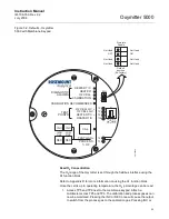
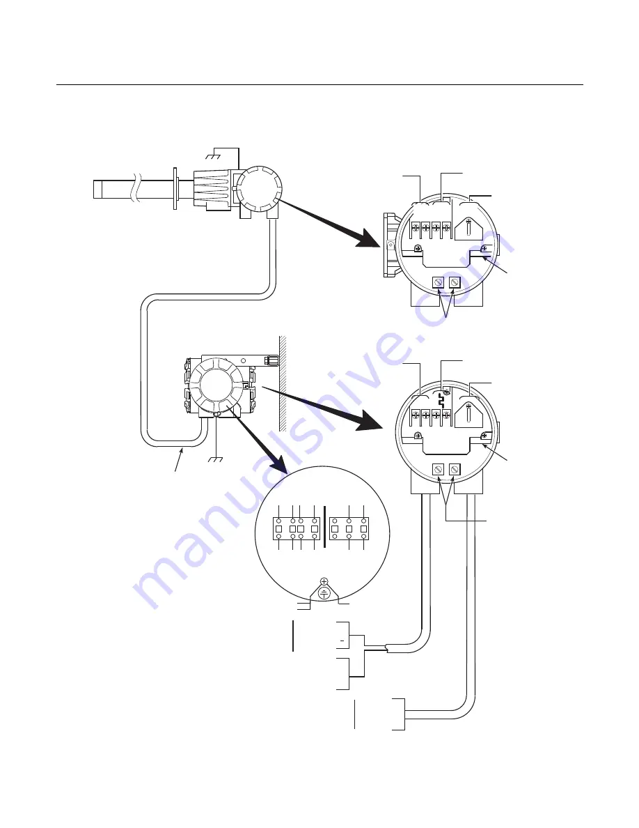
Figure 2-11. Electrical
Installation - Oxymitter 5000 with
Remote Electronics
Oxygen
Signal
+
+
-
-
Terminal
Block
Ground
Lugs
38730105
Fieldbus Digital
Signal
ACL1
ACN
+
+
-
-
4-20
Terminal
Block
Ground Lugs
1
2 3
4
5
6
GRN
ORN
YEL
RED
BLK
BLK
BLU
ORN
YEL
RED
WHT
BLK
HTR
T/C
O
CELL
2
(BY FACTORY)
TO ELECTRONICS
FROM PROBE
BLU
ORN
RED
YEL
BLK
WHT
PROBE
REMOTE
ELECTRONICS
To IMPS 4000 or SPS 4001B
if used. Refer to IMPS 4000
or
Instruction Manual
SPS 4001B
Logic I/O +
Logic I/O -
Line 1
Neutral
Ground
90-250 VAC, 50-60 Hz
Line Voltage Input
Interconnecting
Cable
+
–
Ground
GRN
GRN
GRN
Line Voltage
Calibration
Handshake/
Logic I/O
Heater Power
(Below Cover)
Type K
Thermocouple
Signal
Fieldbus Digital Signal
Fieldbus Digital Signal
Содержание Oxymitter 5000
Страница 2: ......
Страница 6: ......
Страница 12: ......
Страница 22: ...Oxymitter 5000 xii Instruction Manual IM 106 350 Rev 2 2 July 2008 ...
Страница 42: ...Oxymitter 5000 1 20 Instruction Manual IM 106 350 Rev 2 2 July 2008 ...
Страница 62: ...Oxymitter 5000 2 20 Instruction Manual IM 106 350 Rev 2 2 July 2008 ...
Страница 74: ...Oxymitter 5000 4 6 Instruction Manual IM 106 350 Rev 2 2 July 2008 ...
Страница 78: ...Oxymitter 5000 5 4 Instruction Manual IM 106 350 Rev 2 2 July 2008 ...
Страница 94: ...Oxymitter 5000 7 6 Instruction Manual IM 106 350 Rev 2 2 July 2008 ...
Страница 140: ...Oxymitter 5000 9 22 Instruction Manual IM 106 350 Rev 2 2 July 2008 ...
Страница 184: ...Oxymitter 5000 B 2 Instruction Manual IM 106 350 Rev 2 2 July 2008 ...
Страница 204: ...Oxymitter 5000 D 14 Instruction Manual IM 106 350 Rev 2 2 July 2008 ...
Страница 222: ...Oxymitter 5000 E 18 Instruction Manual IM 106 350 Rev 2 2 July 2008 ...
Страница 224: ...Instruction Manual IM 106 350 Rev 2 2 July 2008 Index 2 Oxymitter 5000 ...


