Oxymitter 5000
2-14
Instruction Manual
IM-106-350, Rev 2.2
July 2008
ELECTRICAL
INSTALLATION (WITH
REMOTE
ELECTRONICS)
For Oxymitter 5000 with Remote Electronics
All wiring must conform to local and national codes.
NOTE
To maintain proper earth grounding, ensure a positive connection exists
between the sensor housing, the electronics housing, and earth. The
connecting ground wire must be 14 AWG minimum. Refer to Figure 2-11.
NOTE
Line voltage, signal, and relay wiring must be rated for at least 221°F (105°C).
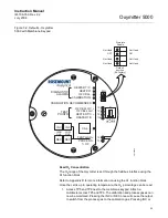
1. Remove cover (31) from remote electronics.
2. Connect Line Voltage.
a. Connect the line, or L1 wire to the L1 terminal and the neutral, or
L2 wire, to the N terminal (Figure 2-11). The Oxymitter 5000
automatically will configure itself for 90-250 VAC line voltage and
50/60 Hz. The power supply requires no setup.
3. Connect fieldbus Digital Signal and Logic I/O Calibration Handshake
Leads, see Figure 2-10. Use individual shielded twisted wire pairs.
Terminate the shield only at the electronics housing.
Disconnect and lock out power before connecting the power supply.
Install all protective covers and safety ground leads after installation. Failure to install covers
and ground leads could result in serious injury or death.
To meet the Safety Requirements of IEC 1010 (EC requirement), and ensure safe operation
of this equipment, connection to the main electrical power supply must be made through a
circuit breaker (min 10 A) which will disconnect all current-carrying conductors during a fault
situation. This circuit breaker should also include a mechanically operated isolating switch.
If not, then another external means of disconnecting the supply from the equipment should
be located close by. Circuit breakers or switches must comply with a recognized standard
such as IEC 947.
The probe and probe abrasive shield are heavy. Use proper lifting and carrying procedures
to avoid personnel injury.
Содержание Oxymitter 5000
Страница 2: ......
Страница 6: ......
Страница 12: ......
Страница 22: ...Oxymitter 5000 xii Instruction Manual IM 106 350 Rev 2 2 July 2008 ...
Страница 42: ...Oxymitter 5000 1 20 Instruction Manual IM 106 350 Rev 2 2 July 2008 ...
Страница 62: ...Oxymitter 5000 2 20 Instruction Manual IM 106 350 Rev 2 2 July 2008 ...
Страница 74: ...Oxymitter 5000 4 6 Instruction Manual IM 106 350 Rev 2 2 July 2008 ...
Страница 78: ...Oxymitter 5000 5 4 Instruction Manual IM 106 350 Rev 2 2 July 2008 ...
Страница 94: ...Oxymitter 5000 7 6 Instruction Manual IM 106 350 Rev 2 2 July 2008 ...
Страница 140: ...Oxymitter 5000 9 22 Instruction Manual IM 106 350 Rev 2 2 July 2008 ...
Страница 184: ...Oxymitter 5000 B 2 Instruction Manual IM 106 350 Rev 2 2 July 2008 ...
Страница 204: ...Oxymitter 5000 D 14 Instruction Manual IM 106 350 Rev 2 2 July 2008 ...
Страница 222: ...Oxymitter 5000 E 18 Instruction Manual IM 106 350 Rev 2 2 July 2008 ...
Страница 224: ...Instruction Manual IM 106 350 Rev 2 2 July 2008 Index 2 Oxymitter 5000 ...

