Instruction Manual
IM-106-350, Rev 2.2
July 2008
4-3
Oxymitter 5000
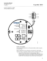
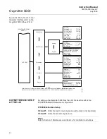
Figure 4-2. Defaults - Oxymitter
5000 with LOI
Read O
2
Concentration
The O
2
range of the Oxymitter is set through the fieldbus interface using the
A1 function block.
Refer to Appendix A for more information on using the A1 function block.
Once the cell is up to operating temperature, the O
2
percentage can be read:
1. To access TP5 and TP6 under the LOI module (Figure 4-2), power
down the Oxymitter 5000 and remove the LOI module. Attach alligator
leads from a multimeter across TP5 and TP6. Install the LOI module
and power up the Oxymitter 5000. Allow time for the cell to reach
operating temperature. The calibration and process gases can now be
monitored.
38730065
SW2
1
2
3
4
TP1
J1
TP2
TP3
RED
YEL
GRN
ORG
TP4
TP5
TP6
Default
position
(Ex-factory)
Simulate
Enable
Not Used
OFF
Not Used
Not Used
Not Used
ON
Not Used
Not Used
Содержание Oxymitter 5000
Страница 2: ......
Страница 6: ......
Страница 12: ......
Страница 22: ...Oxymitter 5000 xii Instruction Manual IM 106 350 Rev 2 2 July 2008 ...
Страница 42: ...Oxymitter 5000 1 20 Instruction Manual IM 106 350 Rev 2 2 July 2008 ...
Страница 62: ...Oxymitter 5000 2 20 Instruction Manual IM 106 350 Rev 2 2 July 2008 ...
Страница 74: ...Oxymitter 5000 4 6 Instruction Manual IM 106 350 Rev 2 2 July 2008 ...
Страница 78: ...Oxymitter 5000 5 4 Instruction Manual IM 106 350 Rev 2 2 July 2008 ...
Страница 94: ...Oxymitter 5000 7 6 Instruction Manual IM 106 350 Rev 2 2 July 2008 ...
Страница 140: ...Oxymitter 5000 9 22 Instruction Manual IM 106 350 Rev 2 2 July 2008 ...
Страница 184: ...Oxymitter 5000 B 2 Instruction Manual IM 106 350 Rev 2 2 July 2008 ...
Страница 204: ...Oxymitter 5000 D 14 Instruction Manual IM 106 350 Rev 2 2 July 2008 ...
Страница 222: ...Oxymitter 5000 E 18 Instruction Manual IM 106 350 Rev 2 2 July 2008 ...
Страница 224: ...Instruction Manual IM 106 350 Rev 2 2 July 2008 Index 2 Oxymitter 5000 ...


