


Instruction Manual
D200156X012
4194HA, HB, HC Controllers
July 2018
55
TAB
HOLE
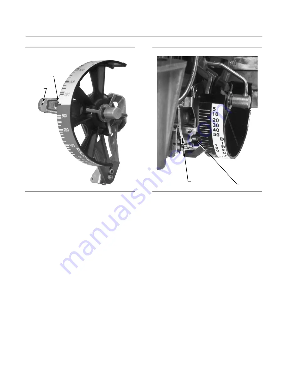
W3761
Figure 5‐10. Proportional Band Adjustment Knob
Alignment
Figure 5‐11. Nozzle‐Flapper Alignment
TOP VIEW
NOZZLE
FLAPPER
W3449‐1
20. Adjust the set point to the minimum value on the process scale.
21. Disconnect link 1 from the drive arm and tape the process indicator to the minimum scale value. Record the
controller output pressure. Output pressure reading can be anywhere from 0.2 to 1.0 bar (3 to 15 psig) for a 0.2 to
1.0 bar (3 to 15 psig) output signal range or 0.4 to 2.0 bar (6 to 30 psig) for a 0.4 to 2.0 bar (6 to 30 psig) output
signal range. If the output is not within the specified range, adjust the flapper leveling screw nearest the nozzle until
the output is within the range specified. See figure 3‐1 for the location of the flapper leveling screws.
22. Adjust the set point to the maximum value on the process scale.
23. Remove the tape and move the process indicator until the controller output equals the pressure recorded in
loosen the shoe adjustment screws (key 30) and move the set point beam shoe (key 29) slightly down from the
center of the flapper assembly (see figure 5‐9).
If the process differential pressure indication in step 27 is at least 2 percent less than the maximum scale value,
move the set point beam shoe (key 29) slightly upward toward the center of the flapper assembly.
scale value.
26. Reattach link 1 to the drive arm.
27. Install the controller assembly in the case and cover.
28. Refer to the flapper alignment procedures.
29. Replace the proportional band indicator cover (key 36) and tighten two screws (key 6).


