10
D, E
# 10 - 24
F, g, H
¼ - 20
J, K, l
¼ - 20
M, N, P, Q, R, T
⅜ - 16
Crosby
STylE JOS-E, JBS-E, JlT*-JBS-E, JlT*-JOS-E ValVES
InstallatIon and MaIntenance InstructIons
6 ValVe MainTenanCe
CauTion
Valves in hazardous fluid service and any other
materials classified as dangerous must be
neutralized immediately after removal from service.
6.1 Visual inspection and neutralizing
a visual inspection shall be made when valves
are first removed from service� The presence
of deposits or corrosive products in the valve
and in the piping should be recorded and
valves should be cleaned to the extent possible
prior to disassembly� Check the condition of
external surfaces for any indication of corrosive
atmospheric attack or evidence of mechanical
damage�
6.2 disassembly
Crosby JOS-E/JBS-E valves should be
disassembled as described below� Parts
identification may be found in Figure 1 on page 2�
The parts from each valve should be marked
properly and segregated to keep them separate
from parts used in other valves�
6.2.1
Remove the cap (40) and cap gasket
(41)� If the valve has a lifting lever device
follow the instructions in Section 6�7�
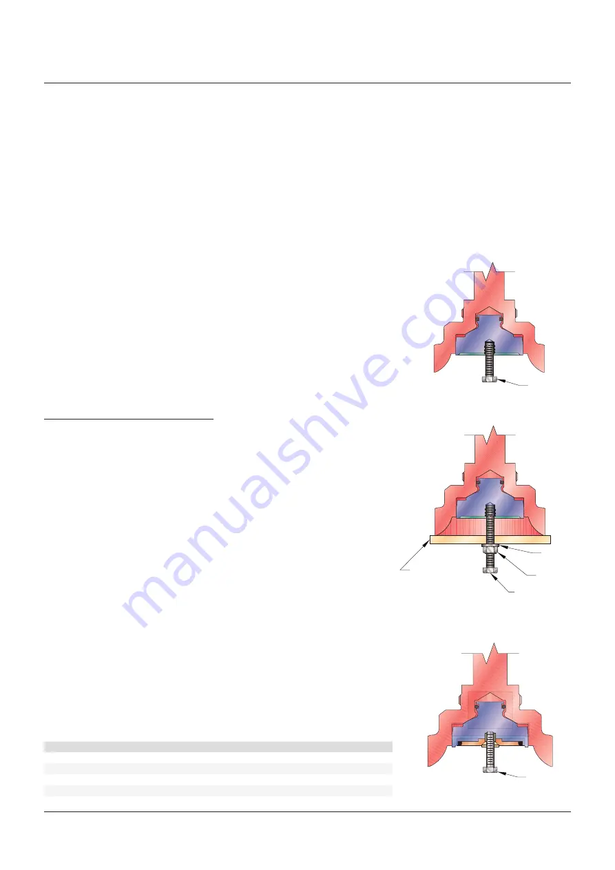
Remove disc insert by pulling on bolt
Remove disc insert by turning nut with wrench
Remove disc insert by pulling on bolt
Bolt
Washer
Rectangular
bar bolt
Nut
Bolt
Bolt
FIguRE 7
FIguRE 6
Table 7 - Jos-e / Jbs-e disc insert
threaded hole sizes
orifice size
shread size (unC)
all of the test fluid passing through an
assembled valve is collected and measured per
the following test procedure:
1� The inlet pressure is adjusted to a
test pressure which is 90% of the cold
differential test pressure� Valves set below
50 psig are tested at 5 psig below the cold
differential test pressure�
2� The test pressure is maintained for a period
of not less than ten minutes�
• Allowable leakage rate
The maximum allowable leakage rate should
not exceed 10 cubic centimeters per hour
per inch of diameter of nominal valve inlet
size� For nominal valve sizes of 1 inch or less,
the leakage rate shall not exceed 10 cubic
centimeters per hour� For soft seated valves
there shall be no leakage for one minute�
• Soft seated valves
For exceptional seat tightness, an O-ring soft
seat design is offered� Refer to Figure 15�
The Crosby soft seat design will provide a valve
that has no visible leakage at a test pressure
of 90 percent of the set pressure or cold
differential test pressure� Soft seated valves
are tested using the same test procedure used
for metal-to-metal seated valves�
6.2.2
Remove the nozzle ring set screw (4)
and set screw gasket (27)� Record
the position of the nozzle ring (3) with
respect to the disc holder (5) by counting
the number of notches required to raise
the ring until it just touches the disc
holder� This information will be needed
again when reassembling the valve�
(Measure the revolutions for P, Q, R and
T orifice Style JlT� See Table 2)�
6.2.3
loosen the adjusting bolt nut (25)� Before
releasing the spring load, make note
of the depth of the adjusting bolt in the
bonnet and count the number of turns
required to remove the spring load� This
information will help when reassembling
the valve to its approximate original setting�
6.2.4
Release all of the spring load by
rotating the adjusting bolt (24) in a
counterclockwise direction�
6.2.5
Remove the bonnet stud nuts (22)�
6.2.6
lift the bonnet (20) straight up to clear
the spindle (16) and valve spring (18)�
Exercise care when lifting the bonnet as
the spring and spindle will then be free
to fall aside�
6.2.7
The spring and spring washers (19) can
now be lifted off the spindle (16)� The spring
and spring washers are fitted together and
must be kept together as a subassembly�
Spring washers are not interchangeable
between ends of the spring�


