Emerson Copeland Scroll YBVH021 1U-3E9 Скачать руководство пользователя страница 33


28 


C6.2.38/0719/E 

6.2  Preparation and work procedure 

A  work  procedure  shall  be  provided  in  the  preparation  stage.  All  maintenance  staff  and  others 
working at the site shall be instructed on the nature of the work being carried out. 

If any work is to be conducted on the refrigeration systems or any associated parts, appropriate fire 
extinguishing  equipment  shall  be  provided.  Dry  powder  or  CO

2

  fire  extinguishers  are  considered 

appropriate. Confirm that appropriate fire extinguishing equipment is available near the work area. 

Work shall be undertaken under a controlled procedure so as to minimize the risk of a flammable 
gas or vapour being present while the work is being performed. 

Prior to starting to work on systems containing flammable refrigerants, safety checks are necessary 
to ensure that the risk of ignition is minimized. 

Avoid working on systems filled with flammable refrigerant in a confined space. 

6.3  Disassembling system components 

When disassembling system components please follow the main steps described hereunder: 

1. 

Recover  refrigerant  and  evacuate  system  using  an  A3-dedicated  recovery  unit  and  vacuum 
pump. All refrigerants shall be recovered to avoid significant release. Ensure that the outlet of 
the vacuum pump is not close to any potential ignition source and that ventilation is available. 

2. 

Flush  system  with  dry  nitrogen.  Compressed  air  or  oxygen  shall  not  be  used  for  purging 
refrigerant systems. 

3. 

Disassemble components with a cutting tool. 

4. 

Drain, recover and dispose of compressor oil as appropriate. 
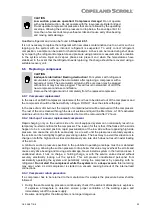
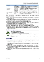
 

To disconnect: 


Using a pipe cutting tool, cut off the suction and discharge 

lines in such a manner that the new compressor can easily be 
re-connected into the system. 


Heat joint areas 2 and 3 slowly and uniformly until the braze 

material  softens  and  the  tube  end  can  be  pulled  out  of  the 
fitting. 

To reconnect: 


Recommended  brazing  material:  Silfos  with  minimum  5%  silver  or  silver  braze  used  on  other 
compressors. 


Due to the different thermal properties of steel and copper, brazing procedures may have to be 
changed from those commonly used. 

NOTE: Since the discharge stub contains a check valve, care must be taken not to overheat 
it to prevent brazing material from flowing into it. 

6.4  Provisions of legislation and leak check requirements 

According to EN 378-4, systems with a refrigerant charge above 3 kg shall be subject to tightness 
inspection at  least on  an  annual  basis. The  owner/operator shall  keep an  updated  logbook  of  the 
refrigerant system containing all details with regard to maintenance and repair works (quantities and 
type of refrigerant changed or transferred, system components changes and replacements, etc.). 

The F-gas Regulation (EU) No 517/2014 contains additional requirements depending on the system 
and stipulates training requirements for alternative refrigerants. 

6.5  Exchanging the refrigerant 


WARNING 
Air/R290 mixture! Flammable atmosphere! Explosion hazard!

 In any case 

avoid air/R290 mixture in the refrigeration system. Make sure that the system 
is  filled  with  pure  R290  refrigerant.  In  the  event  that  the  refrigerant  needs 
replacing,  the  charge  should  be  recovered  using  R290  qualified  refrigerant 
recovery unit and recycling bottles. 


Figure 20: Tube connecting areas


Содержание Copeland Scroll YBVH021 1U-3E9

Страница 1: ...Copeland Scroll Variable Speed Horizontal Refrigeration Compressors for R290 Applications Application Guidelines ...

Страница 2: ...sible pressure temperature and relative humidity ranges 7 2 6 6 Application limits Operating envelope 7 2 6 7 Design features 9 2 7 Dimensions 10 3 Installation 11 3 1 Compressor and drive handling 11 3 1 1 Compressor transport and storage 11 3 1 2 Compressor positioning and securing 11 3 1 3 Installation location 11 3 2 Compressor mounting parts 11 3 3 Compressor brazing procedure 12 3 4 Suction ...

Страница 3: ...on 23 5 4 Preliminary checks Pre starting 24 5 5 Charging procedure 24 5 6 Run in time 25 5 7 Initial start up 25 5 8 Start and stop routine 25 5 9 Starting sound 25 5 10 Deep vacuum operation 25 5 11 Shell temperature 25 5 12 Shell temperature 25 5 13 Pump down cycle 25 5 14 Minimum run time 26 5 15 Shut off sound 26 5 16 Oil level 26 6 Maintenance repair 27 6 1 Qualification of workers 27 6 2 Pr...

Страница 4: ...C6 2 38 0719 E 6 8 Oil additives 31 7 Troubleshooting 32 8 Dismantling disposal 35 DISCLAIMER 35 ...

Страница 5: ......

Страница 6: ... in systems according to instructions and conform to the corresponding provisions of legislation For relevant standards please refer to the Manufacturer s Declaration available at www climate emerson com en gb NOTE Emerson marks all A3 scroll compressors with a sticker for flammable refrigerants Systems using such refrigerants must comply with applicable legislation and regulations such as but not...

Страница 7: ...nnel protection must be observed Use personal safety equipment Safety goggles gloves protective clothing safety boots and hard hats should be worn where necessary 1 3 General instructions WARNING Pressurized system Serious personal injuries and or system breakdown Accidental system start before complete set up must be avoided Never leave the system unattended without locking it out electrically wh...

Страница 8: ...nd the matched pairs have been designed for maximum efficiency and reliability The drive will power the compressor control the compressor running speed provide compressor and drive protection and communicate with the master controller in ModBus RTU protocol The drive requires cooling and is typically installed in the unit near the compressor To optimize drive efficiency and to limit electromagneti...

Страница 9: ...eration outside the designed parameters which in turn increases overall system reliability 2 4 Compressor and drive nomenclature The compressor and drive model designation contains the following technical information Figure 1 Nomenclature 2 5 BOM Variations The Bill Of Material indication at the end of the compressor designation describes the different compressor layouts and details YBVH compresso...

Страница 10: ...ith an external oil sight tube The factory oil filling for all YBVH compressor models has been optimized to a value of 600 ml which corresponds to a level between 116 mm and 75 mm on the external oil sight tube The oil level should be within these limits for all applications All YBVH compressors are equipped with a positive displacement twin oil pump The oil sump is located on the lower end of the...

Страница 11: ...ce for all future systems with the same design Perform the test anew to check the oil return behaviour again as described above If the oil level rises above the maximum level compressor performance could start to drop due to the extra amount of oil This situation will not harm the compressor but it is recommended to remove the extra oil quantity in order to reach the nominal range Repeat the test ...

Страница 12: ...es in operation YBVH 30 95 No condensing 30 C 50 C 30 C 60 C Table 5 Allowable ambient temperature and humidity ranges for the compressor 2 6 6 Application limits Operating envelope CAUTION Inadequate lubrication Compressor breakdown Copeland scroll compressors are qualified for operation inside the envelope published by Emerson The envelope is defined according to Emerson s testing and experience...

Страница 13: ...m the system to the compressor also see Chapter 2 6 3 Oil filling and oil level The use of 1500 rpm for low condensing and high evaporating temperatures is possible as shown in the envelope The system should be able to bring the compressor to a point inside the envelope as fast as possible at the start and to keep the compressor running there Running outside the envelope is not allowed At start up...

Страница 14: ...rive feature aims to protect the drive and the compressor It cannot be used in the system as an operating envelope limitation The operating envelopes published in these guidelines are qualified for a minimum superheat of 10K The maximum superheat at high evaporating temperature should not exceed 20K NOTE Operate matched pairs of compressor and drive combinations only NOTE Before first start each d...

Страница 15: ...38 0719 E 2 7 Dimensions The external dimensions of YBVH compressors are shown in Figures 8 9 below Figure 8 YBVH compressors external dimensions top view Figure 9 YBVH compressors external dimensions side view ...

Страница 16: ...e discharge connection plug should be removed first before pulling the suction connection plug to allow the dry air pressure inside the compressor to escape Pulling the plugs in this sequence prevents oil mist from coating the suction tube making brazing difficult The copper coated steel suction tube should be cleaned before brazing The compressor plugs must be removed as late as possible before b...

Страница 17: ...l suction injection and discharge tubes These tubes are far more robust and less prone to leaks than copper tubes Due to the different thermal properties of steel and copper brazing procedures may have to be changed from those commonly used Refer to Figure 12 and procedure below for the brazing of the suction discharge and injection lines to a Scroll compressor For systems with A3 flammable refrig...

Страница 18: ...humidity environment Liquid floodback must be monitored during reversing valve operation especially when coming out of defrost Excessive floodback occurs when the sump temperature drops below the safe operation line shown in the oil dilution chart see Figure 5 If an accumulator has to be used the oil return orifice should be from 1 to 1 4 mm in diameter depending on compressor size and compressor ...

Страница 19: ...rant flow direction the suction and discharge pressures will go outside of the operating envelope The condition will usually cross the diagonal line representing the lower right hand side corner of the envelope The sound that the compressor makes during this transition period is normal and the duration of the sound will depend on the coil volume outdoor ambient and system charge Since Copeland scr...

Страница 20: ...three phase motor due to their inherently higher starting torque This phenomenon like the one described previously can easily be avoided by using standard line isolation techniques Since the variable speed scroll has a broad running frequency range 25 92 Hz it is almost impossible to avoid all of the natural frequencies that may exist in the system piping The system designer must carefully evaluat...

Страница 21: ... parts must be used The grounding screw must be torqued to 2 4 to 2 6 Nm Add a cable strain relief device Protect cable and wires against sharp edges 4 2 Electrical installation WARNING Conductor cables Electrical shock Shut off power supply before undertaking any task on electrical equipment WARNING Ignition source in a potentially flammable atmosphere Fire hazard The electrical connection could ...

Страница 22: ...nd the cable connectors Always shut off power supply before attaching or removing the molded plug cable from the connection pins The molded plug connector must be smoothly pushed by hand towards the connection pins of the compressor Never use a tool to knock the molded plug connector on the terminal pins as this could damage the glass inserts of the pins It is mandatory to secure the molded plug c...

Страница 23: ...molded plug power cable to the compressor circle fence Attach the molded plug connector to the compressor connection pins Smoothly push the molded plug connector by hand as far as possible towards the pins Never use a tool to knock the molded plug as this could damage the glass inserts of the pins Secure the connection with the retainer 4 2 4 Removing the molded plug power cable Shut off power sup...

Страница 24: ...switch RCD Residual current device D Drive assembly S1 Auxiliary switch F1 F6 Fuses F3 HP limiter F4 LP switch Figure 17 Wiring diagram for YBVH compressors with single phase drive Power circuit Control circuit Legend B1 System controller K2 Contactor optional Q1 Main switch RCD Residual current device D Drive assembly S1 Auxiliary switch F1 F6 F7 F8 Fuses F3 HP limiter F4 LP switch Figure 18 Wiri...

Страница 25: ... Watts DC of heating to serve as a crankcase heater The crankcase heating function activation is recommended when the system charge exceeds the refrigerant charge limit indicated in Table 6 below If this function is required the crankcase heating function must be used and the power has to be determined by tests across the envelope for winter and summer situations Compressor Refrigerant charge limi...

Страница 26: ...stomer shall follow all applicable regulations and standards to apply appropriate control to ensure that the pressure is always above the required minimum limit 4 7 Discharge gas temperature protection IMPORTANT Inadequate lubrication Scroll set damage All YBVH compressors must be equipped with an external discharge gas temperature protection A good system control shall prevent the system from ope...

Страница 27: ...rating map for maximum operating discharge line temperatures Figure 19 Discharge temperature sensor mounting 4 8 High potential testing WARNING High potential testing in a flammable atmosphere Fire hazard Make sure the atmosphere is non flammable before performing high potential testing Do not perform any high potential test when the compressor is charged with flammable refrigerant WARNING Conduct...

Страница 28: ...he LPT not exceeding the low side PS 5 2 Compressor tightness test WARNING High pressure Personal injuries Consider personal safety requirements and refer to test pressures prior to test CAUTION System contamination Bearing malfunction Use only dry inert gases for example nitrogen for leak testing DO NOT USE other industrial gases The compressor has been leak tested in the Emerson factory As the c...

Страница 29: ...ed Correctly charged with refrigerant Compressor electrical auxiliary switch location and position 5 5 Charging procedure WARNING Air R290 refrigerant mixture in a potentially flammable atmosphere Explosion hazard Only use filling equipment designed and approved for use and operation with R290 Make sure all connections are tight to avoid leakage Make sure to fill with pure R290 CAUTION Low suction...

Страница 30: ...e over traditional on off control of fixed capacity units For more information about this topic please refer to the Emerson User Manual for ED3 5 9 Starting sound During the very brief start up a clicking sound is audible resulting from initial contacting of the spirals this sound is normal Due to the design of the Copeland scroll compressors the internal compression components always start unload...

Страница 31: ...ts per hour There is no minimum off time because scroll compressors start unloaded even if the system has unbalanced pressures The most critical consideration is the minimum run time required to return oil to the compressor after start up To establish the minimum run time a sample compressor equipped with a sight tube can be ordered from Emerson for oil return qualification and minimum oil level s...

Страница 32: ...ing out work in relation to a refrigeration system which involves exposing any pipe work shall use any sources of ignition in such a manner that it may lead to the risk of fire or explosion All possible ignition sources shall be kept sufficiently far away from the site of installation repairing removing and disposal during which refrigerant can possibly be released to the surrounding space Open fl...

Страница 33: ...ressor oil as appropriate To disconnect Using a pipe cutting tool cut off the suction and discharge lines in such a manner that the new compressor can easily be re connected into the system Heat joint areas 2 and 3 slowly and uniformly until the braze material softens and the tube end can be pulled out of the fitting To reconnect Recommended brazing material Silfos with minimum 5 silver or silver ...

Страница 34: ...rest of the oil is cleaned through the use of suction and liquid line filter driers A 100 activated alumina suction line filter drier is recommended but must be removed after 72 hours 6 6 2 Start up of a new or replacement compressor Rapid charging only on the suction side of a scroll equipped system can occasionally result in a temporary no start condition for the compressor The reason for this i...

Страница 35: ...rned each compressor has to be packed individually NOTE Check with your transport company that all the requirements that apply to such shipments are complied with 6 7 Lubrication and oil removal WARNING Air R290 refrigerant mixture in a potentially flammable atmosphere Fire hazard Use suitable recovery unit and recycling bottles also for oil disposal as R290 refrigerant may still be solved in the ...

Страница 36: ... high hygroscopicity of the POE oil To determine the actual moisture content of the lubricant samples have to be taken from the system and analysed 6 8 Oil additives Although Emerson cannot comment on any specific product from our own testing and past experience we do not recommend the use of any additives to reduce compressor bearing losses or for any other purpose Furthermore the long term chemi...

Страница 37: ... voltage falls below 90 of the nameplate voltage the motor may develop insufficient torque Make sure the compressor is supplied with rated nominal voltage Defective capacitor or relay For a single phase motor a defective capacitor or relay may prevent the compressor from starting Check these components by substituting a known to be good component if available Make sure that the capacitors are elec...

Страница 38: ...ncrease discharge pressure This is also true for an undersized condenser Correct the component selection as needed Check the fan motor make sure it is running properly in the right direction Check the condenser if dirt has been accumulated it will clog the airflow clean as necessary High discharge pressure is also caused by an overcharged system and high ambient temperature surrounding the condens...

Страница 39: ...plied Correct it as necessary Control circuit inoperative Check the thermostat measure the temperature of the room and compare with the thermostat replace or re calibrate the thermostat Check the LP control switch and replace it if it is found defective Compressor lubrication problem Oil trap due to incorrect piping layout sizing Check the piping layout design Installations of pipe being routed ov...

Страница 40: ...cooling For air cooled drives make sure that the airflow is not obstructed EMI filter Check all the wiring and check for loose or burned contacts on the board Compressor Make sure the compressor is running within the envelope Check the winding resistances from the compressor motor and the cables between compressor and drive Check for loose or burned contacts 8 Dismantling disposal Removing oil and...

Страница 41: ...th Dubai UAE Tel 971 4 811 81 00 Fax 971 4 886 54 65 mea sales emerson com ASIA PACIFIC Suite 2503 8 25 F Exchange Tower 33 Wang Chiu Road Kowloon Bay Kowloon Hong Kong Tel 852 2866 3108 Fax 852 2520 6227 CZECH REPUBLIC Hajkova 22 CZ 133 00 Prague Tel 420 733 161 651 Fax 420 271 035 655 Pavel Sudek emerson com SPAIN PORTUGAL C Pujades 51 55 Box 53 ES 08005 Barcelona Tel 34 93 412 37 52 iberica sal...

Отзывы: