111
ADVANCED USER GUIDE
IP66/Nema 4X variable speed drive
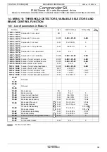
MENU 12: THRESHOLD DETECTORS, VARIABLE SELECTORS AND BRAKE CONTROL FUNCTION
CONTROL TECHNIQUES
3854 en - 03.2008 / b
to
: Not used
to
: Not used
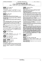
: Brake release
Adjustment range : 0 or 1
Indicates the state of the brake control output.
0 (Disabled) (OFF): The brake is applied.
1 (Enabled) (On): The brake is released.
: Brake controller
Adjustment range : 0 to 3
Factory setting
: 0
Used to enable brake control and to select to which digital
output it will be assigned.
0 (Disabled) (dis): Brake control is not enabled.
1 (On contactor) (COnt): Brake control is enabled and
directed towards the integrated brake contactor option.
2 (On relay) (rEI): Brake control is enabled and directed
towards the relay. In this case, the "drive healthy" indication
is rerouted to digital output DIO1 (
8.27
=
12.40
and
8.21
=
10.01
).
3 (User select) (USEr): Brake control is enabled. The output
is not assigned automatically; it is up to the user to select the
destination for parameter
12.40
.
WARNING: The safety function overrides brake control. If
8.10
= 1 then
12.41
= 2, brake control is enabled, but the
relay remains assigned to
10.01
"Drive healthy" and
12.41
changes to 3 "User select". Consequently, disable
the safety function by
8.10
= 0 before setting
12.41
= 2.
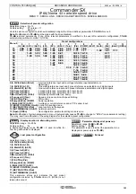
: Upper current threshold
Adjustment range : 0 to 200%
Factory setting
: 10%
Used to set the current threshold at which the brake will be
controlled. This current level should provide sufficient torque
at the time the brake is released.
: Lower current threshold
Adjustment range : 0 to 200%
Factory setting
: 10 %
Used to set the current threshold below which brake control
will be disabled (brake engaged). It should be set so that loss
of the motor power supply is detected.
: Brake release frequency
Adjustment range : 0 to 20.0 Hz
Factory setting
: 1.0 Hz
Used to set the frequency threshold at which the brake will be
controlled. This frequency level should ensure sufficient torque
is provided to drive the load in the right direction when the
brake is released. This threshold is usually set at a value
slightly above the frequency corresponding to the motor slip at
full load.
Example: - 1500 rpm = 50 Hz
- Rated on-load speed = 1470 rpm
- Slip = 1500 - 1470 = 30 rpm
- Slip frequency = 30/1500 x 50 = 1 Hz
: Brake apply frequency or
speed
threshold
Adjustment range : 0 to 20.0 Hz
, 0 to 100 rpm
Factory setting
: 2.0 Hz
, 5 rpm
Used to set the frequency or speed threshold at which brake
control will be disabled. This threshold enables the brake to
be applied before zero speed so as to avoid load veering
while the brake is being engaged.
If the frequency or speed drops below this threshold when no
stop request has been made (change of direction of rotation),
brake control will remain activated. This exception can be
used to avoid the brake being applied as the motor passes
through zero speed.
: Pre-brake release delay (
)
Brake apply delay (
)
Adjustment range : 0 to 25.00 s
Factory setting
: 0.10 s
and 0.30 s
: This time delay is triggered when all the conditions for
brake release have been met. It allows enough time to
establish an adequate level of reactive current in the motor
and to ensure that the slip compensation function is fully
activated. When this time delay has elapsed, brake control is
enabled (
12.40
= 1).
For the full duration of this time delay, the ramp applied to the
reference is held constant (
2.03
= 1).
: This time delay is used to delay the brake apply
command in relation to the passage below the minimum
speed threshold (
12.45
). It is useful for avoiding repeated
oscillation of the brake when it is being applied around zero
speed.
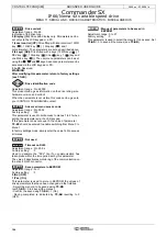
: Post-brake release delay
Adjustment range : 0 to 25.00 s
Factory setting
: 0.10 s
This time delay is triggered when brake control is enabled. It
is used to allow time for the brake to release before unlocking
the ramp (
2.03
= 0).
: Brake apply delay
Adjustment range : 0 to 25.00 s
Factory setting
: 0
This time delay is used to maintain the torque at standstill
(
6.08
= 1) while the brake is applied. When this time delay
has elapsed, the drive output is deactivated.
: Position controller during brake release (
)
Adjustment range : 0 or 1
Factory setting
: 0
0 (Disabled) (OFF): The ramp is held when the drive
output is not active, until the post-brake release delay
(
12.47
) has expired. This allows the speed reference to
remain at 0 until the brake is released.
1 (Enabled) (On): Position controller enabled while the ramp
is held. This function avoids the load moving during the brake
release phase.
Function not available.
: Not used
: Forced brake release
Adjustment range : 0 or 1
Factory setting
: 0
0 (Disabled) (OFF)
1 (Enabled) (On)
When the drive output is active (
10.02
= 1), the brake control
output
12.40
is enabled when the release conditions
determined by the brake control are met. When the drive
output is inactive, the brake control output
12.40
is forced to
1 if
12.51
is at 1.
12.16
12.22
12.36
12.39
12.40
12.41
12.42
12.43
12.44
12.45
12.46
12.47
12.48
12.49
12.50
12.51
Содержание Commander SX
Страница 1: ...Part Number Commander SX IP66 Nema 4X variable speed drive Advanced user Guide 3854 en 03 2008 b ...
Страница 139: ......
Страница 140: ......

