


The Smartpack S Controller
User Guide •
Smartpack S Controller
11
350030.013, 1v0-2012-06
CAN Bus Termination
To ensure a correct bus communication and avoid data reflection, you must always
terminate the CAN bus with two 120Ω resistors
, one at each end of the line (60Ω
bus impedance).
Smartpack S
-based DC power systems are shipped from factory with the CAN bus
already terminated with 120Ω resistors. The CAN bus termination is implemented
with a special RJ45 plug with built-in 120Ω end-of-line resistor.
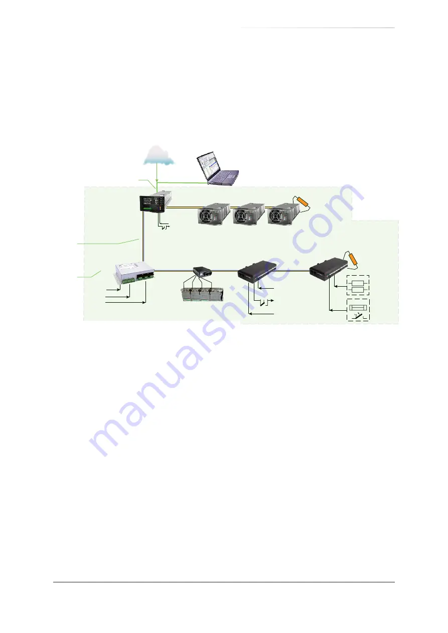
Figure 4. Example of CAN bus addressing and termination in a Flatpack S power sys-
tem with Smartpack S-based control system and some CAN nodes connected
the CAN bus
When connecting more CAN nodes to the bus, you have to remove the CAN bus
termination plug from one of the CAN bus ends, and plug it in one of the CAN ports
on the last connected CAN node.
CAN Bus Cabling
In addition to the two dedicated wires for communication, the CAN bus multi-wire
cable must integrate wires for the CAN power supply and other signals. In standard
industrial environments, the CAN bus can use standard cabling without shielding
or twisted pair wiring. If very low interference (EMI) is required, a CAT-5 twisted-pair
cable is recommended.
Smartpack S
Controller
Flatpack S
HE Rectifiers
Load Monitor
120Ω
End-of-Line
Resistor
120Ω
End-of-Line
Resistor
Current
Monitoring
Sense Inputs
AC Voltage & Current
Sense Inputs
Temp, Fan Speed
Mon & Ctrl
Config Inputs
Battery string #1
Alarm Outputs
NC-C-NO
Config. Inputs
Shunts
Fuse
Monitoring
Config. Inputs
Fuses
01
02
49
I/O Monitor
81
Battery Monitor
33
AC Mains Monitor
97
n
1
WebPower
(Web-based user interface)
Internal System Monitoring
and external I/O signals
Ethernet
cable (LAN)
ID number
CAN Bus
cable
Flatpack S DC Power System (Telecom or Industrial App)
Internet