Chapter 3
Installation
MAN_105G_1.16
Page 76
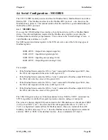
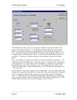
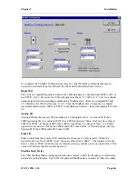
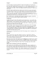
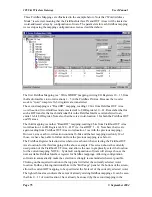
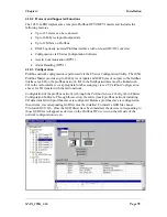
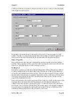
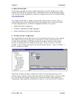
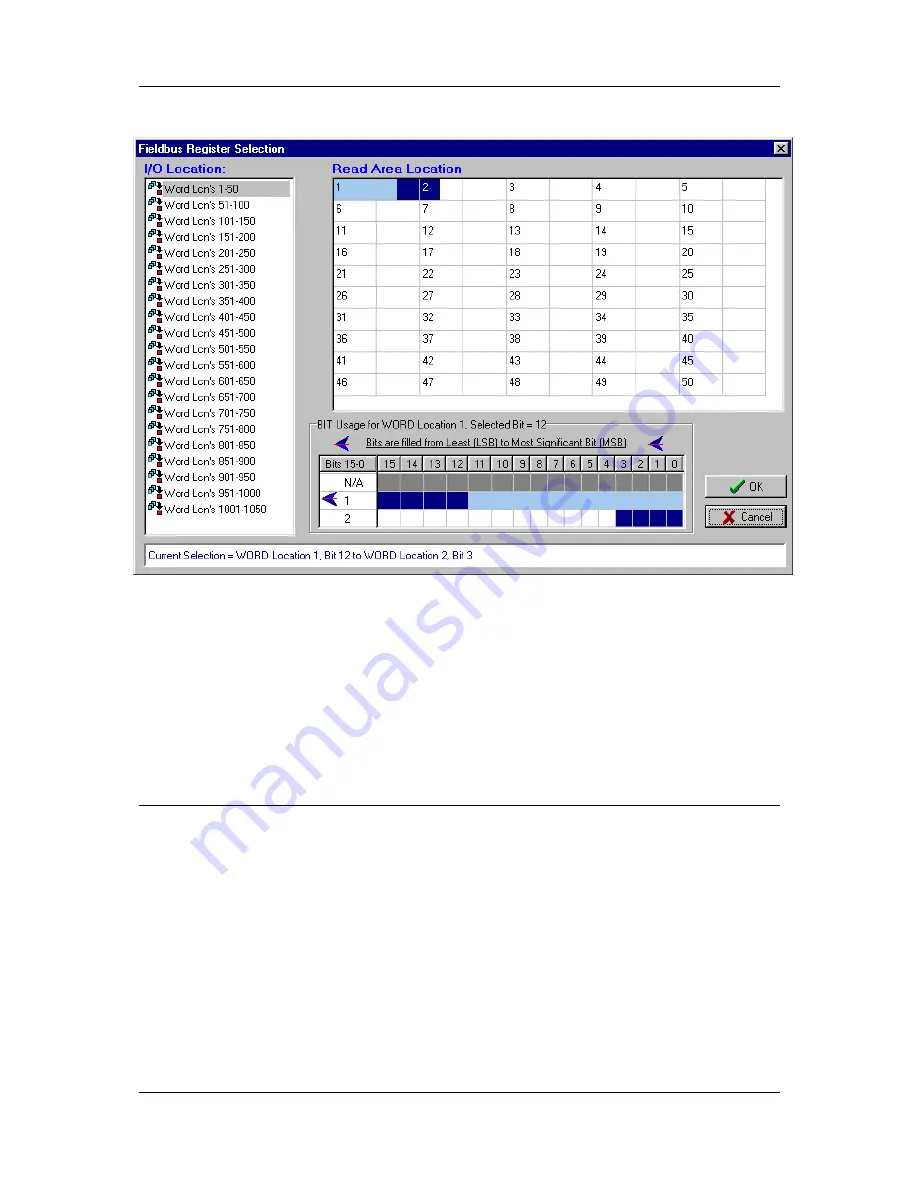
example). The dark blue area in the register selection screen above shows the extent and
location of the current fieldbus mapping graphically. The status panel at the bottom of the
window always displays the extent of the current selection, which can be seen to be word 1,
bit 12 to word 2, bit 3.
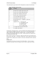
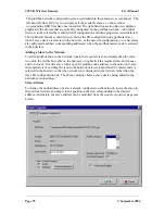
A status location (4500) may be used to give the host device status information about the
Fieldbus Interface. This register will be value 0x0000 if the Fieldbus Interface is “on-line”
and communicating with the fieldbus, or value 0xFFFF if it is “off-line”. If you wish to use a
status register, select the “Enable Status Location” box. This register could be mapped to a
remote module or local output as an alarm.
4.9
Fieldbus Configuration - Profibus Slave
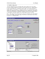
The Profibus 105U-G-PR1 acts as a Profibus DP Slave - the host device is a Profibus
Master. If you use the 105U-G with a PLC, the PLC configuration tool will require a GSD
file so it can recognize the Profibus interface in the 105U-G. This file loads into the PLC
configuration software (for example, Siemens STEP 7). The file is available on the same CD
as the configuration software or from the Elpro web page www.elprotech.com.
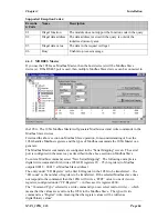
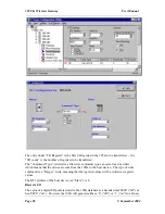
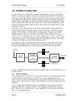
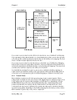
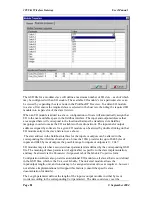
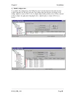
Configuration of the Profibus Fieldbus Interface comprises allocating a Profibus Slave
address to the 105G, and configuring links between the Radio Interface and the Fieldbus
Interface (i.e. Fieldbus Mappings).
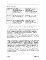
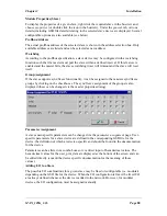
The Profibus address can be set in the “Fieldbus Config” screen or via the rotary switch on
the end-plate of the module- valid slave addresses are 1 – 126. If the “Enable Rotary
Switch” box is not selected, then the address entered in the program will be used and the
rotary switch value ignored. If the “Enable Rotary Switch” box is selected, then the address

