background image

105U-G Wireless Gateway

User Manual

Page 43

© September 2004

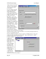
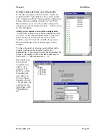
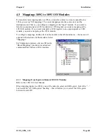
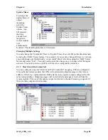
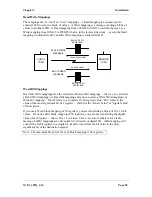
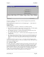
When you have selected the
project, a screen will appear
where you may enter the

system address.

If you are editing an existing
project, the system address
will already have been
entered.  Do not change the
system address unless you are
going to re-program all of the
modules in the system.

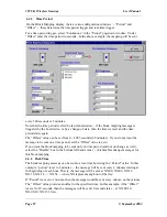
Password

.   You have the

option of entering a password
to protect the configuration
files against unauthorized
changes.  When you open a
new project, you will be asked
to enter a password  -  if you
do not enter any text  -  that is,
press “ESC” or “Enter”, then
password protection is
disabled.  If you do enter a
password, then you will need
to enter this password to
access the project.  Without
the password, you are unable access the project

The password can be between 6 and 256 characters.  You can also change password at any
time by over-typing the passowrd.

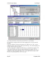
If you are starting a new project, you have the option of “Enabling Security”. This option
enables encryption of the data sent over the radio.  -  please read Section 4.2.2 and the
associated warnings before using this option.

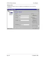
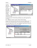
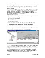
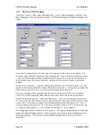
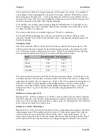
To proceed with the
configuration,
double-click on the
project name on the
menu on the left side
of the screen.
“Units” will appear.
You can now enter
the types of units
which will be used
in the system.  If you
double-click on
“Units”or select the
“+” sign beside
“Units”, then the
modules that have
already been created will be displayed.

Содержание 105U-G

Страница 1: ...ELPRO Technologies Pty Ltd 9 12 Billabong Street Stafford Q 4053 Australia Tel 61 7 33524533 Fax 61 7 33524577 Email sales elprotech com Web www elprotech com User Manual 105U G Wireless Gateway ...

Страница 2: ...odule We trust it will give you many years of valuable service ATTENTION Incorrect termination of supply wires may cause internal damage and will void warranty To ensure your 105G enjoys a long life double check ALL your connections with the user s manual before turning the power on ...

Страница 3: ...d using the aerial and equipment configuration described in the 105U Installation Guide Check with your local 105G distributor for further information on regulations 2 For 105G modules operation is authorised by the radio frequency regulatory authority in your country on a non protection basis Although all care is taken in the design of these units there is no responsibility taken for sources of e...

Страница 4: ...nties This warranty does not indemnify the purchaser of products for any consequential claim for damages or loss of operations or profits and ELPRO is not liable for any consequential damages or loss of operations or profits resulting from the use of these products ELPRO is not liable for damages losses costs injury or harm incurred as a consequence of any representations warranties or conditions ...

Страница 5: ...T 105G LINK 23 2 4 1 Modbus DF1 23 2 4 2 Profibus 23 2 4 3 Ethernet 24 2 5 RADIO SYSTEM DESIGN 24 2 5 1 Radio Signal Strength 24 2 5 2 Repeaters 25 2 6 RADIO COMMS FAILURE 25 2 6 1 Monitoring Communications Failure 26 2 7 SECURITY CONSIDERATIONS 26 Chapter 3 INSTALLATION 28 3 1 GENERAL 28 3 2 ANTENNA INSTALLATION 28 3 2 1 Dipole antenna 29 3 2 2 Yagi antenna 30 3 3 POWER SUPPLY 31 3 3 1 AC Supply ...

Страница 6: ... CONFIGURATION PROFIBUS SLAVE 76 4 10 FIELDBUS CONFIGURATION PROFIBUS MASTER 77 4 10 1 GSD File 77 4 10 2 Protocol and Supported Functions 78 4 10 3 Configuration 78 4 10 4 Message Interface 89 Error Codes 109 DPV1 Return Codes 110 4 11 FIELDBUS CONFIGURATION ETHERNET 111 4 11 1 Setting IP Address 111 4 11 3 EtherNet IP 116 4 12 FIELDBUS CONFIGURATION DEVICENET 120 4 12 1 DeviceNet Introduction 12...

Страница 7: ...105U G Wireless Gateway User Manual Page 7 September 2004 Chapter 7 WARRANTY 145 Appendix 1 STATUS REGISTERS 146 Appendix 2 IT Functionality 148 ...

Страница 8: ... to PLC s DCS SCADA or Internet Wireless extension of factory automation buses such as Profibus Wireless interconnectivity between different fieldbuses Ethernet to Profibus to Modbus to DF1 Combined networks of the above The 105U G has eight on board discrete I O Each I O point can be configured individually as a contact input signal or a discrete output signal Input signals can sent via its field...

Страница 9: ...st equipment DF1 full duplex is a peer to peer protocol Either DF1 device can initiate commands to the other device and both devices will respond to commands from the other device The 105U G MD1 has two serial connections RS232 and RS485 on the bottom end plate of the module The serial port provides both RS232 and RS485 hardware connections however both connections are paralleled internally both c...

Страница 10: ...is 440 this exceeds the capacity of the Profibus interface Master unit PR2 The Profibus master interface supports 2048 input bytes and 2048 output bytes Each byte can be 8 discrete inputs or outputs but analog or pulse I O take up 1 byte for low resolution values 8 bit or 2 bytes for high resolution values 16 bit So a Profibus Master 105G can handle up to 4300 I O total but analog or pulse inputs ...

Страница 11: ... Each byte can represent 8 discrete inputs or outputs or an 8 bit value or two bytes can represent a 16 bit value That is analog or pulse I O can be transferred as 8 bit registers 1 byte or 16 bit registers 2 consecutive bytes An output is a value coming into the 105G via the fieldbus that is a value written to the 105G from the DeviceNet master An input is a value going out from the 105G via the ...

Страница 12: ...ination address sending a return acknowledgment Up to five attempts are made to transmit the message if an acknowledgment is not received The ELPRO 105U protocol is designed to provide reliable radio communications on an open license free radio channel The Fieldbus port enables communications between a host device which could be a PLC DCS HMI intelligent transducer etc and the 105G Radio Interface...

Страница 13: ...5U G MD1 unit as this unit uses the RS485 port for Modbus or DF1 communications unless this unit is configured as Repeater only and does not have a host device connected 1 3 The Wireless Network The 105G can communicate with up to 490 other addresses this could be 490 other 105U modules or in the case of 105K modules it could be many thousands of modules as many 105K modules can share the same add...

Страница 14: ...register can be configured with an update time 105G modules can transmit to 105G modules as well as other 105G modules There can be multiple 105G and 105C modules in a network as well as 105U I O Because the 105U protocol is peer to peer there are few constraints on communications between multiple 105U modules Poll Messages A 105G can also generate poll messages to remote 105U modules These poll m...

Страница 15: ...time period configurable 1 4096 sec 1 1 hour or real time clock or on demand by the host device by writing to a trigger register in the 105G Block Write Message A block write message transmits a consecutive block of register values from one 105G to a destination 105G It can be triggered by time period configurable 1 4096 sec 1 1 hour or real time clock or on demand by the host device by writing to...

Страница 16: ...nsmits each message in the same format A data concentrator collects the I O values as a block and transmits the complete block in one transmission 1 3 4 105G Repeaters Any 105U module can repeat a normal radio message however only 105G modules can repeat a block message 105G units connected to a host device can also act as a repeater for other modules Where a 105G is being used without a host devi...

Страница 17: ...tive signal in a reset condition off or 0 for a time equal to the number of remote addresses or modules configured times 5 seconds plus any delay if remote addresses are offline For example if there are 20 remote addresses configured in the 105G database then the active signal will be held in the reset state for 100 seconds 20 x 5 During this period the 105G will not change any output values in it...

Страница 18: ...e and a sensitivity The 105G will transmit a message to the configured remote output whenever the I O register value changes by the sensitivity amount if it has not changed within the update time the 105G will send a message anyway The 105G will make five attempts to send a message if it does not receive an acknowledgment from the remote module then the I O register is given a comms fail status wh...

Страница 19: ...mber 8001 5000 3001 If the register value is greater than 32767 then the 15th bit is set indicating that the output has a communications failure On board I O and Internal I O The 105G has eight discrete I O points These may be used as inputs or as outputs Inputs are linked to registers 4300 4307 That is if a contact connected to DIO1 is on then register 4300 is given an on value Outputs are contro...

Страница 20: ...put value DIO 1 4320 Output value DIO 1 4301 Input value DIO 2 4321 Output value DIO 2 4302 Input value DIO 3 4322 Output value DIO 3 4303 Input value DIO 4 4323 Output value DIO 4 4304 Input value DIO 5 4324 Output value DIO 5 4305 Input value DIO 6 4325 Output value DIO 6 4306 Input value DIO 7 4326 Output value DIO 7 4307 Input value DIO 8 4327 Output value DIO 8 4308 Low battery voltage status...

Страница 21: ... communications I O in the Radio Interface is linked to I O in the Profibus Interface in a flexible way via ESeries Configuration Software The Profibus Slave interface provides a total of 416 I O bytes with a maximum 244 input bytes and maximum 244 output bytes A Profibus byte can contain 8 discrete binary values or two bytes can be used for a 16 bit analogue or pulse register So the Profibus inte...

Страница 22: ...can have up to 31 x 105S modules connected to it These modules are addressed 96 127 More than one 105S module can have the same address provided they are not connected to the same 105U module that is 100 via 16 is identified as a different module to 100 via 65 A constraint that needs to be considered is the capacity of the radio channel If there is too much traffic on the radio channel then the sy...

Страница 23: ... to that remote output The comms fail status resets when a successful transmission occurs For I O registers which have been mapped from a remote input or another 105G a comms fail time period may be configured If a radio message for this I O register has not been received within this time then this registers comms fail status is set The comms fail status will reset when a message is received for t...

Страница 24: ... the comms status of one I O point at each remote module if this point is in comms fail then all points at the remote module will be in comms fail If this point is an input then the comms fail time for this input can be made short to give an early warning of a comms problem this means that the corresponding update time for the input at the 105U will need to be short If the point is an output then ...

Страница 25: ...U G Wireless Gateway User Manual Page 27 September 2004 modules can understand each other Foreign modules will hear the messages but cannot decrypt the messages For more information refer to section 4 2 2 ...

Страница 26: ... which may be reliably achieved will vary with each application depending on the type and location of antennas the degree of radio interference and obstructions such as hills or trees to the radio path Please refer to your distributor for the expected maximum distance to comply with local radio regulations Where it is not possible to achieve reliable communications between two 105 modules then a t...

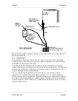
Страница 27: ...tenna and coaxial cable should be carefully taped to prevent ingress of moisture Moisture ingress in the coaxial cable is a common cause for problems with radio systems as it greatly increases the radio losses We recommend that the connection be taped firstly with a layer of PVC Tape then with a vulcanising tape such as 3M 23 tape and finally with another layer of PVC UV Stabilised insulating tape...

Страница 28: ...e should be located on the bottom of the installed antenna The Yagi antennas may be installed with the elements in a vertical plane vertically polarised or in a horizontal plane horizontally polarised For a two station installation with both modules using Yagi antennas horizontal polarisation is recommended If there are more than two stations transmitting to a common station then the Yagi antennas...

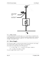
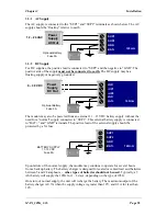
Страница 29: ...llinear antenna looks similar to the dipole except that it is longer 3 3 Power Supply The 105G power supply is a switch mode design which will accept either AC or DC supply The module includes an integral battery charger for a backup battery The module accepts supply voltages in the following ranges 12 24 volts AC RMS or 9 30 volts DC at the supply terminals or 10 8 15 volts DC at the battery term...

Страница 30: ...ive lead of the external supply should be protected by a 5A fuse Upon failure of the normal supply the module may continue to operate for several hours from a backup battery The battery charger is designed for sealed or vented lead acid batteries between 5 and 24 amphours other types of batteries should not be used Typically a 5 Ahr battery will supply the 105G for 1 2 days depending on the type o...

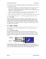
Страница 31: ...for low battery status and also battery voltage If a 24V solar supply is used the 24V battery should be connected as a DC supply SUP1 and GND the supply voltage can be monitored however the supply fail voltage will activate too low to be used as a battery fail status 3 4 Input Output The 105G has eight on board discrete digital I O These act as both discrete inputs and discrete outputs 3 4 1 Digit...

Страница 32: ...232 Serial Port The serial port is a 9 pin DB9 female and provides for connection to a terminal or to a PC for configuration field testing and for factory testing It is also used by the Modbus DF1 version for fieldbus connection This port is internally shared with the RS485 ensure that the RS485 is disconnected before attempting to use the RS232 port Communication is via standard RS232 signals The...

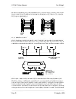
Страница 33: ... drop network Note that the RS485 port is shared internally with the RS232 port make sure that the RS232 port is disconnected before using the RS485 port RS485 is a balanced differential standard but it is recommended that shielded twisted pair cable be used to interconnect modules to reduce potential RFI An RS485 network should be wired as indicated in the diagram below and terminated at each end...

Страница 34: ... position to connect the resistor If the module is not at one end of the RS485 cable the switch should be off It is important to maintain the polarity of the two RS485 wires On the 105G terminal A the terminal on the right is positive and terminal B is negative ...

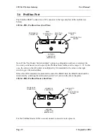
Страница 35: ... switch is multiplied by 10 and added to the value on the right switch to give the node address Where the 105G module is mounted at the end of the RS485 link the RS485 link should be terminated by switching the termination switch on down in the above diagram 105U G PR2 Profibus Master End Plate For the Profibus Master 105G a second unused connector is also present ANTENNA CONNECTION 869MHz Only PR...

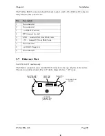
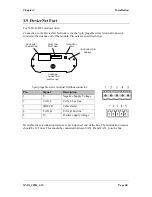
Страница 36: ...est to send 5 GND Isolated GND from RS485 side 6 5V Isolated 5V from RS485 side 7 Not connected 8 ve RS485 Negative 9 Not connected 3 7 Ethernet Port For 105U G ET1 modules only The Ethernet connection uses a standard RJ45 connector on the top end plate of the module The selector switches should all be off in the diagram below off is up ANTENNA CONNECTION 869MHz Only RJ45 ETHERNET CONNECTION SELEC...

Страница 37: ... connector located at the antenna end of the module Pin outs are outlined in the table below See section on configuration for description of selector switches Modbus Plus 9 pin D SUB Connector Pin Name 1 Cable Shielding 2 MBP Line B 3 MBP Line A Housing PE ANTENNA CONNECTION 869MHz Only D9 MODBUS PLUS CONNECTION SELECTOR SWITCHES DIAGNOSTIC LED s CONFIGURATION ENABLE ...

Страница 38: ...le screw terminal fieldbus connector Pin Signal Description 1 V Negative Supply Voltage 2 CAN_L CAN_L bus line 3 SHIELD Cable shield 4 CAN_H CAN_H bus line 5 V Positive supply voltage DeviceNet uses termination resistors at each physical end of the bus The termination resistor should be 121 ohm This should be connected between CAN_H and CAN_L on the bus ANTENNA CONNECTION 869MHz Only DEVICENET CON...

Страница 39: ... by entering the correct password a security encryption key used to encrypt and decrypt radio messages This is an optional feature If selected the configuration program will offer a random security key or this can be over written with your own key A key is a string of any 8 ASCII characters Each module in the project is configured with a unit address Each module must have a unique unit address wit...

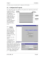
Страница 40: ...wn below 4 2 1 Program Operation Start the software by either clicking on the start bar and navigating to the Configuration menu or by running ESERIES EXE in the directory selected in the setup stage The Initial screen will appear From the initial screen you can select an existing project or start a new project The name of the project will create a new folder which will eventually contain the conf...

Страница 41: ...isabled If you do enter a password then you will need to enter this password to access the project Without the password you are unable access the project The password can be between 6 and 256 characters You can also change password at any time by over typing the passowrd If you are starting a new project you have the option of Enabling Security This option enables encryption of the data sent over ...

Страница 42: ...stem configuration click on Units on the left hand menu and then Add Unit Select the type of module from the list For 105G modules you will be asked to select the bus protocol This must match the 105U G module type you have installed You have the option of selecting a unit address for the module or allowing the program to select one automatically If you choose to select the unit address the progra...

Страница 43: ...105U G Wireless Gateway User Manual Page 45 September 2004 Deleting a Unit A module can be deleted from the configuration by highlighting the unit and selecting Delete Unit ...

Страница 44: ...e sensitive The security key will never be displayed If you do not enable security there will be no data encryption of the radio messages This is the default setting If a security key has been entered this key is downloaded into each module as part of the configuration download process You can download another configuration at any time if the security key is different or if there is no security ke...

Страница 45: ... recorded in the archived configuration files and therefore the configuration files should be held in a secure place and backed up The security key does not prevent a hacker uploading a configuration from a module and downloading with a new security key This module will no longer operate with other modules in the system To prevent this unauthorised access to modules must be prevented If you lose t...

Страница 46: ...u want to transfer a 105G register to an output signal at a 105U module you enter a mapping at the 105G module To configure mappings double click on the module in the left hand menu the menu will expand with selections for that module Select Mappings Each mapping comprises only one I O point Block Mappings provide more advanced communications between 105G modules 4 3 1 Mappings from Inputs at Remo...

Страница 47: ...the inputs and select the first I O register in the range The selected mappings will be entered with consecutive I O registers For each remote input configured to a 105G there is a comms fail time parameter in the 105G If the 105G does not receive a message destined to that I O register within the comms fail time then the comms fail status for that I O register will be set the most significant bit...

Страница 48: ...he list The comms fail time should be greater than the update time of the remote input 4 3 2 Mappings from 105G to Outputs at Remote 105U I O Modules Mappings can be entered in the 105G to remote outputs Select the Mappings option under the 105G Select an I O register and select the remote module and the output channel To map several consecutive I O registers to several outputs select the first I ...

Страница 49: ... message is sent the update period restarts You can configure the amount of change required to trigger a change message this is called the change sensitivity Sensitivities are configured for blocks of I O registers that is each I O register does not have a unique sensitivity You can configure up to 50 sensitivity values that is there can be 50 blocks of registers with different sensitivities For m...

Страница 50: ...lock all entries using the Shift Select feature and select Edit You only need to enter the change once to change all of the inputs selected This feature is also available with the other configurable parameters 4 3 3 Don t Send if in Comm Fail You can configure a special Don t Send if in Comms Fail mapping If this is configured for a particular remote module the 105G will not transmit output messag...

Страница 51: ...the following events based on a configurable time period based on real time clock on demand by the host device For information on this configuration refer to the next section on Block Mappings 4 4 Mappings from 105G to other 105G Modules Individual links between 105G modules can be configured under the Mappings selection as described in the previous section For example if you want to transfer I O ...

Страница 52: ...ng Word refers to a complete 16 bit register value Bit refers to the value of the most significant bit of a register this bit is the binary value or digital value of the register If you use a Word block mapping of 50 registers you are transferring a block of 50 x 16 bit values If you use a Bit block mapping of 50 registers you are only transferring the digital value of each register that is 50 x 1...

Страница 53: ...n the above example the block of registers will be 110 124 15 registers starting at I O Reg 110 If you are entering a Write mapping then the values in this block will be sent to another 105G If it is a Read mapping then values from another 105G will be sent to this block Under Destination Gateway enter the I O Register this is the first register in the block You do not need to enter the block size...

Страница 54: ...ings If a value in the block changes by more than the sensitivity amount then the block message will be sent You can enter a delay period such that the message is sent after the delay period Combinations of the above triggers can occur for example the block mapping message will be sent if a change of state occurs AND at the configured real time AND when the host device writes to the trigger regist...

Страница 55: ...do not want the message to be sent on a time period set the Offset value to zero If you want the block mapping to be sent only on time period and not on change as well select the Disable box in the bottom left hand corner this disables change messages for this block mapping 4 4 4 Real Time The block mapping message can be sent at a real time by setting the Period value In this example period is se...

Страница 56: ...tem Clock Location Set Location Days 4330 4340 Hours 4331 4341 Minutes 4332 4342 Seconds 4333 4343 The clock registers are used by the 105G for the real time clock trigger The host device can read these registers The host device can also set the 105G clock at any time by writing to the appropriate Set register The Set registers are 4340 4343 The procedure for setting the real time clock via these ...

Страница 57: ...s If you do not wish change messages to occur select the Disable box 4 4 6 Mixing Normal Mappings and Block Mappings Block mappings can include I O Registers already used with normal I O mappings For example a remote 105U I O module could map a remote input to I O Reg 743 At the 105G the host device could read I O Reg 743 and you could also configure a block mapping including this register to anot...

Страница 58: ...or blocks of I O registers that is each I O register does not have a unique sensitivity You can configure up to 50 sensitivity values that is there can be 50 blocks of registers with different sensitivities In the above example three sensitivity blocks have been configured 1 I O registers 0 49 have a sensitivity of 1000 or 1 5 of the 16 bit range 2 I O registers 100 499 have a sensitivity of 250 o...

Страница 59: ...ad the radio channel A sensitivity value of 1 in 65535 is a change of 0 0015 If the host device writes an analogue value to a 105G every 100msec it will change by at least 1 bit each time A small sensitivity value will cause a change message to be sent every 100msec If there are many analogue values in the same situation then there would be many change messages every 100msec Sensitivity values for...

Страница 60: ...og 16 bit For example If the Modbus Master sends the 105G a read command for Modbus input 10457 then the 105G will respond with the value in I O register 457 If the Modbus Master sends the 105G a write command for Modbus output 02650 then the 105G will write the value to I O register 2650 If the Modbus Master sends the 105G a read command for Modbus input 30142 then the 105G will respond with the ...

Страница 61: ...ple digital output points ON or OFF 16 Set multiple output registers Analog I O are 16 bit register values A value of decimal 8192 hex 2000 represents 0mA A value of 49152 hex C000 represents 20mA Each 1 mA has a value of 2048 hex 0800 a change of 4096 hex 1000 is equivalent to a change of 2mA A 4 20mA signal will vary between 16384 hex 4000 and 49152 hex C000 A 0 20mA signal will vary between 819...

Страница 62: ...bus commands the 105G Master can generate The Modbus Master commands are configured in the Serial Mapping screen The serial port is configured in the same way as described in the above section on Modbus Slave To enter a Modbus command select New Serial Mapping The following example is a digital write command which writes 105G I O registers 20 25 6 registers to Modbus outputs 00012 00017 at Modbus ...

Страница 63: ...he Modbus Slave to return the values of 10 registers which will be stored in I O registers 463 473 in the 105G As the command is a register read command the target Modbus locations will be of the type 3xxxx The starting location is 30001 So the values of locations 30001 30010 in Modbus Slave 1 will be transferred to I O registers 463 473 in the 105G The CF Register comms fail register acts as a di...

Страница 64: ...he remote 105U modules are 16 bit register value A value of 8192 hex 2000 represents 0mA A value of 49152 hex C000 represents 20mA Each mA has value of 2048 hex 0800 a change of 4096 hex 1000 is equivalent to a change of 2mA A 4 20mA signal will vary between 16384 hex 4000 and 49152 hex C000 A 0 20mA signal will vary between 8192 hex 2000 and 49152 hex C000 Pulse I O Pulse counts from the remote 1...

Страница 65: ...esponse is not received to the first message When a response is eventually received the 105G will reset the value in Comms Fail image location to 0 and the normal re try sequence will operate Different I O Commands can use different Comms Fail image locations however we recommend that you use the same image location for all I O Commands to the same Modbus slave address 4 7 Serial Configuration DF1...

Страница 66: ... registers An Integer has a signed 16 bit value 32768 to 32767 A Long Integer has a 32 bit value The 105G registers contain an unsigned 16 bit value 0 to 65535 We recommend that you use Long Integer read write commands the upper 16 bits of the 32 bit value will be ignored Refer to more information in the Analogue I O and Pulse I O sections below The PLC2 uses unsigned 16 bit registers in the same ...

Страница 67: ...mand you can select read or write which means that the values are sent from the 105G to the host device The type of write command is a Integer write meaning that the register values will be written as register values The DF1 address of the host device or Slave is 2 Discrete I O The value of a digital I O point is stored in the 105G database as a hexadecimal 0000 off or hex FFFF on However the 105G...

Страница 68: ...n from an integer file in an SLC or Micrologix CPU integer files contain 16 bit signed values These represent values in the range 32768 to 32767 The data values from the 105U modules are treated as 16 bit unsigned values To convert the data from an analogue input move the data from the integer file to a long file MOV command then mask out the high 16 bits MVM with mask value FFFF This will result ...

Страница 69: ... location can hold 8 digital inputs or outputs Analog or pulse values can be stored as a low resolution 8 bit value a single fieldbus location or as a high resolution 16 bit value two consecutive fieldbus locations To optimize I O usage the 105G provides a flexible method of data transfer between the Radio Interface and the Fieldbus Interface The user configures links between the Radio Interface a...

Страница 70: ...e below 4 8 2 Transfer Mode Radio Interface registers are all 16 bit general purpose input or output registers That is analog inputs or outputs are stored as a 16 bit value Digital inputs or outputs occupy a whole 16 bit register and are stored as either 0000 hex or FFFF hex for compatibility with the ELPRO Radio Protocol However the Fieldbus Interface may contain depending on the protocol signifi...

Страница 71: ...analog values in low resolution in cases where I O space is at a premium Byte Address Mode is recommended when using byte transfer mode see Address Mode section below Bit transfer mode operates on only the most significant BIT of Radio Interface registers but allows these bits to be consecutively packed in the Fieldbus Interface This mode would suit the transfer of digital I O in cases where it is...

Страница 72: ...or response message Fieldbus mappings to from the IN OUT areas should always start at location 0 if possible or the lowest available unused location Configuration Software will always automatically choose the next lowest available location it is strongly recommended that this topology be used so as not to place unnecessary processing overhead on the module 4 8 4 Fieldbus Mapping Configuration The ...

Страница 73: ...Registers 4320 4327 i e local DOT 1 8 Note here that we are again reading from Fieldbus OUT Area word location 1 as with the previous mapping However since each word location contains 16 bits and the last mapping used only 12 of those we have been able to follow on from the previous mapping see below The Fieldbus Register Selection screen below was shown when selecting the Fieldbus OUT Area locati...

Страница 74: ...ve The Profibus 105U G PR1 acts as a Profibus DP Slave the host device is a Profibus Master If you use the 105U G with a PLC the PLC configuration tool will require a GSD file so it can recognize the Profibus interface in the 105U G This file loads into the PLC configuration software for example Siemens STEP 7 The file is available on the same CD as the configuration software or from the Elpro web...

Страница 75: ...bit refer next section An application note for configuring a Siemens S7 PLC to communicate with a Profibus 105G can be downloaded from the Elpro web site www elprotech com 4 10 Fieldbus Configuration Profibus Master The 105U G PR2 implements a complete Profibus DPV0 DPV1 master The hardware is optimized for high throughput and can be used in mono or multi master networks up to 12 Mbit s Up to 125 ...

Страница 76: ...es of outputs in the fieldbus interface for I O on the profibus network I O in the fieldbus interface must be linked with I O in the radio interface via appropriate fieldbus mappings see 4 8 Fieldbus Configuration above for I O transfer with the radio network Configuration of the profibus network is through the Profibus Network Config tab in ESeries Configuration Software Through this section the ...

Страница 77: ...rofibus master node is selected in the busview Adding a Slave to the Network To add a profibus slave to the network locate the required slave and simply drag the slave icon onto the visible bus cable on the busview or right click the required slave and choose add to network To add a slave with a specific profibus node address to the network locate the required slave and drag the icon to the networ...

Страница 78: ...ionality it can be assigned to the masters sync freeze groups by clicking on the checkboxes The sync freeze assignment of the groups is also displayed these can be changed via the master properties dialog Parameter Assignment A slaves user specific parameters can be changed via the parameter assignment page User specific parameters for a slave device are defined in the corresponding GSD file for t...

Страница 79: ...that I O module entry in the slave listview see above The start address in the fieldbus interface for the inputs or outputs can be altered in the corresponding Start field as shown above Since the 105G provides for up to 2048 bytes of inputs and 2048 bytes of outputs the possible range for inputs or outputs is 0 2047 I O modules may also have associated user parameter data defined by the correspon...

Страница 80: ...fibus address of the profibus master default 0 Only available addresses are listed and can be selected as new address The serial baud rate for the entire profibus network is selected this is the baud rate that will be used by the master and therefore must also be supported by all slave devices on the network Most slaves will support auto baud rate detect but it should be ensured that any slave on ...

Страница 81: ...a that slaves module properties group assignment configuration may be synchronized using the Message Interface instruction SET_SLAVE_MODE see section on the Message Interface below Bus Parameters Tab The bus parameters can be adjusted only when the selected profile is user defined see Profibus Tab above These parameters should only be changed if the user is familiar with the individual profibus pa...

Страница 82: ...termines the length of time elapsing in the node between a data frame being received and a response occuring 1 t_bit Tset 494 t_bit Tqui The quiet time is the time a modulator needs after recognizing a send frame to switch from send to receive 0 t_bit Tqui MIN 31 t_bit Min Tsdr 1 Gap Factor The Gap Factor determines how many token rounds occur before a new active node master can be added to the to...

Страница 83: ...ble time for a token pass During this time all active nodes masters obtain the token one time to send data ESeries Config Software calculates an optimized Ttr depending on the values of other bus parameters If an individual bus parameter is changed pressing the Recalculate button recalculates the Ttr including Delta_Ttr Watchdog The watchdog determines the watchdog time transferred to slaves if th...

Страница 84: ...adio Configuration I O or Block Mappings 1 Profibus Network Configuration Once the GSD file for the profibus slave has been installed the slave device can be added to the profibus network see Configuration section above For this example the slave is a modular device therefore we add the necessary I O modules to the slave The example requires 8 x digital points to be transferred to the slave hence ...

Страница 85: ...x digital outputs are all contained in a 1 Byte Out module we use Single Bit Mode for the fieldbus write mapping The configured mapping see below transfers the 8 x I O Registers 100 107 in the radio interface to single bits in Fieldbus Location 0 of the fieldbus interface corresponding to the Output Address of the corresponding 1 Byte Out module The 1 x analog input to be read from the slave must ...

Страница 86: ...ow been transferred to the radio interface must be mapped over the radio network The analog input from the slave is mapped to an analog output at a remote 105U 1 the 8 x digital output at the profibus slave will be activated in this example via appropriate mapping from 8 x digital input at a remote 105U 4 see below ...

Страница 87: ...e Message Interface Area of the 105G I O Registers radio interface Since the message interface is part of the radio interface it may be controlled either remotely via appropriate block mappings i e remote 105G or locally via a device on the profibus network i e configuration tool PLC or other smart device The supported messages are listed in the table below Message Description SET_SLAVE_MODE Send ...

Страница 88: ...length of the message data The message data may be up to 128 x 16bit registers in length and contain data that is specific to the particular message Offset Register 0 Message ID 1 Message Information 2 Command Number 3 Data Size 4 Extended Word 1 5 Extended Word 2 6 Extended Word 3 7 Extended Word 4 8 Extended Word 5 9 Extended Word 6 10 Extended Word 7 11 Extended Word 8 12 Message Data up to 139...

Страница 89: ...sage is a command or a response 0 Response Message 1 Command Message Error Code If the Err bit is set this field contains additional error information 0h Invalid Message ID 1h Invalid Message Type 2h Invalid Command 3h Invalid Data Size 4h 6h Message header malformed 8h Invalid Response 9h Flash Config Error Fh Invalid Other All other values are reserved Message Type This field specifies the messa...

Страница 90: ... Area i e Messages from Profibus Interface 4850 4899 Spontaneous Message OUT Area i e Alarm Messages from Profibus 4900 4949 Spontaneous Alarm ACK IN Area i e ACK to above For example a message could be sent to the Profibus Interface by constructing the required message in the Message IN Area either via radio using appropriate block mapping s or locally via a host device or configuration tool This...

Страница 91: ...mmand Similarly a freeze control command causes the addressed slaves to assume freeze mode In this operating mode the states of the inputs are frozen until the master sends the next freeze command Freeze mode is concluded with the unfreeze command Note Not all slaves supports this feature Consult the documentation for the actual slave for further information Command and response layout Command Res...

Страница 92: ... send Bit Explanation 0 LSB Reserved set to zero 1 Reserved set to zero 2 Unfreeze input data 3 Freeze input data 4 Unsynchronize output data 5 Synchronize output data 6 Reserved set to zero 7 MSB Reserved set to zero Fault Information Extended Fault Information If Invalid Other is returned in the Message Information word in the header of the response information about the fault can be found here ...

Страница 93: ...ended Word 6 Extended Word 7 Extended Fault Info Extended Word 8 Fault Information Response data word 1 Station Status 1 Station Status 2 Response data word 2 Station Status 3 Master Address Response data word 3 Ident Number Response data word 4 Response data word n Extended Diagnostic Data Slave Address Range 1 125 specifies the slave to read diagnostics from Type of request 0x00 Internal slave d...

Страница 94: ...ormation Fault Information Extended Fault Information If Invalid Other is returned in the Message Information word in the header of the response information about the fault can be found here Fault Information contents Extended Fault Information contents 0001h Address out of range 0018h DPMC_M_START has not yet occurred DPMC_ERR_M_NOT_ALLOWED 000Ah Failed to read Diagnostic Data from slave 002Bh Bu...

Страница 95: ... Extended Word 5 Err Code1 Err Code2 Extended Word 6 Err Code3 Err Code4 Extended Word 7 Return Code Extended Word 8 Fault Information Message data byte 1 Slave Data 1 Slave Data 1 Message data byte n Slave Data n Slave Data n Current Slave Address Range 1 125 specifies the current address of the slave New Slave Address Range 1 125 specifies the new address of the slave Slave Ident Number Ident nu...

Страница 96: ...t Information If Invalid Other is returned in the Message Information word in the header of the response information about the fault can be found here 0001h Current slave address out of range 0002h New slave address out of range 000Ah Failed to execute request See Return Code for additional fault information 000Bh Remote station failure See Return Code for additional fault information 00FFh Module...

Страница 97: ...ord 5 Extended Word 6 Extended Word 7 Return Code Extended Word 8 Fault Information Response data byte 1 Station Type 0 Response data byte 2 Station Type 1 Response data byte 127 Station Type 126 Station Type 0 126 00h Slave Station 01h Master Station not yet ready for Token ring station only physically at the bus 02h Master Station ready to enter Token ring there is not yet any Token transmission...

Страница 98: ...ed Word 7 Return Code Extended Word 8 Fault Information Response data byte 1 Data 1 Response data byte 2 Data 2 Response data byte n Data n Slave Address Station address of the slave responder Slot Number Slot Index Used in the slave to address the desired data block Length This parameter specifies the number of bytes of the data block that has to be read If the server data block length is less th...

Страница 99: ... about the fault can be found here 0001h Address out of range 000Ah Failed to execute MSAC1_Alarm_Ack request 000Bh Remote station failure 0010h Remote Station DPV1 Failure see Error Decode below 00FFh Module not initialised Error Decode Error Code 1 Error Code 2 If Fault Information contains error code 0010h more information according to the DPV1 specification can be found here ...

Страница 100: ...nded Word 6 Err Code1 Err Code2 Extended Word 7 Return Code Extended Word 8 Fault Information Message data byte 1 Data 1 Data 1 Message data byte n Data n Data n Slave Address Station address of the slave responder Slot Number Slot Index Used in the slave to address the desired data block Length This parameter specifies the number of bytes that has to be written If the destination data block size ...

Страница 101: ...001h Address out of range 000Ah Failed to execute MSAC1_Alarm_Ack request 000Bh Remote station failure 0010h Remote Station DPV1 Failure see Error Decode below 0011h Too much data is sent to the slave more than Max_Channel_Data_Len 00FFh Module not initialised Error Decode Error Code 1 Error Code 2 If Fault Information contains error code 0010h more information according to the DPV1 specification ...

Страница 102: ... trigger the module to send an MSAC1_Alarm_Ack to the slave This will tell the slave that the master has configured the alarm The slave will in turn respond with a confirmation message see Alarm Confirmation MSAL1_ALARM_CON below Command and response layout Command Response Message ID ID ID Message Information 4002h 0002h Command Number 0022h 0022h Data Size request length 0000h Extended Word 1 Sl...

Страница 103: ...ds an alarm message with Extended Diag flag set 00h Slave sends an alarm message with Extended Diag flag cleared Data 1 n Additional manufacturer specific alarm information Alarm PDU Fault Information If the Message Information word in the header of the message indicates Invalid Other additional information is available in this register 003Eh Module has received an invalid alarm indication data st...

Страница 104: ...r 0023h Data Size 0000h Extended Word 1 Slave Add Slot No Extended Word 2 Seq Number Alarm Spec Ack Extended Word 3 Alarm Type Ext Diag Extended Word 4 Extended Word 5 Error Decode Extended Word 6 Err Code1 Err Code2 Extended Word 7 Return Code Extended Word 8 Fault Information Slave Address Station address of the slave that indicates the alarm Slot Number Used by the slave to indicate the source ...

Страница 105: ...h Extended Diag flag cleared Fault Information If Invalid Other is returned in the Message Information word in the header of the response information about the fault can be found here 000Ah Failed to execute MSAC1_Alarm_Ack request 000Bh Remote station failure 0010h Remote Station DPV1 Failure see Error Decode below Error Decode Error Code 1 Error Code 2 If Fault Information contains error code 00...

Страница 106: ...RR_V1C_TIMEOUT Active request terminated with timeout 8028h DPMC_ERR_V1C_INVALID_LEN Invalid length in user request 8030h DPMC_ERR_V1C_REQ_NEG Negative indication from lower layer 8031h DPMC_ERR_V1C_REQ_RE Message frame format error in response 8042h DPMC_ERR_V1C_REQ_WITHDRAW Request was recalled 8043h DPMC_ERR_V1C_REQ_NOT_FOUND Associated request block not found 80C1h DPMC_ERR_V1C_MM_FE Format er...

Страница 107: ...lues according to the DP standard may be available in Error Code 1 See below Consult the Profibus DP specification for information on how to interpret these status values Error Code Name Meaning 01h L2_STATUS_UE 02h L2_STATUS_RR 03h L2_STATUS_RS 0Ch L2_STATUS_RDL 0Dh L2_STATUS_RDH 0Fh L2_STATUS_NA Consult Profibus DP Specification ...

Страница 108: ..._M_SLAVE_NOT_FOUND Slave does not respond 0031h DPMC_ERR_M_TIMEOUT Active request terminated with timeout 0034h DPMC_ERR_M_INVALID_LEN Invalid length in user request 0035h DPMC_ERR_M_REQ_NEG Negative indication from lower layer 0036h DPMC_ERR_M_REQ_RE Message frame format error in response 0037h DPMC_ERR_M_REQ_WITHDRAW Request was recalled 0038h DPMC_ERR_M_REQ_NOT_FOUND Associated request block no...

Страница 109: ...TP Server The module features a flexible HTTP server with SSI functionality This enables the user to configure a web interface or web page accessing I O values in the 105G Email Client SMTP The application can send email messages using the Mailbox interface Predefined messages stored within the file system can be sent triggered by a specified I O value in the 105G It is also possible to include I ...

Страница 110: ...lue of 255 correspond to the subnet ID Conversely the IP Address values directly above a subnet mask value of 0 correspond to the host ID So in this example the subnet ID is 169 254 100 and the host ID is 175 Special case IP addresses Devices on an Ethernet network are not allowed to be configured to the following IP addresses therefore do not configure the module to use any of them 0 x x x IP add...

Страница 111: ...Bit 2 Read Input discretes 1 IN OUT Bit 3 Read multiple registers 0 IN OUT Word 4 Read input registers 1 IN OUT Word 5 Write coil 1 OUT Bit 6 Write single register 1 OUT Word 7 Read exception status 1 15 Force multiple coils 2 OUT Bit 16 Force multiple registers 0 OUT Word 22 Mask write register 2 OUT Word 23 Read Write registers 2 IN OUT Word Supported Exception Codes Exception Code Name Descript...

Страница 112: ...5 16382 16383 16384 1023 1024 16369 16370 16371 16382 16383 16384 OUT Area Modbus TCP Addresses Fieldbus READ Locations 0 1023 Modbus Bit Address OUT Area Loctn Modbus Word Address Bit 15 Bit 14 Bit 13 Bit 2 Bit 1 Bit 0 0 1025 16385 16386 16387 16398 16399 16400 1 1026 16401 16402 16403 16414 16415 16416 1022 2047 32737 32738 32739 32750 32751 32752 1023 2048 32753 32754 32755 32766 32767 32768 As...

Страница 113: ...odbus Coil or Modbus Word addresses corresponding to configuration software as well as the correct function code see 4 10 2 Supported Commands Appropriate Modbus prefixes may need to be added to the Modbus Address depending on the host device For example a word write fieldbus mapping in the 105G to Modbus location 10 can be read by a host device as 30010 30000 for an input register 10 as the addre...

Страница 114: ...ilable on the same CD as the configuration software or on the ELPRO web site Implemented Objects EtherNet IP requires some mandatory objects these are implemented as well as some vendor specific objects The mandatory objects are the ones in the specification from ODVA The following vendor specific objects are implemented I O data input mapping object Class A0h I O data output mapping object Class ...

Страница 115: ...uld then be available via Ethernet IP in class 04h Instance Attribute 64h or in class A0h Instance Attribute 1 If the Disable option is checked the I O transfer will not be made available to Ethernet IP The table below shows the possible IO Instances and their corresponding Ethernet IP locations IO Instance Assembly Object Vendor Specific Object IO Input Instance 1 6 Class 04h Instance 64h 69h Cla...

Страница 116: ...ngle The data produced is configured from fieldbus write mappings to I O Input Instance 2 6 Array of USINT Note This data is also available in the vendor specific object I O Data Input Mapping Object Class A0h Instance Attribute 01h and Attribute ID s 01h to 06h see I O Data Input Mapping Object Output Area Instance 96h ID Name Service Description Type 03h Data Get_attribute_single Set_attribute_s...

Страница 117: ...e_single The data produced is configured from fieldbus write mappings to I O Input Instance 6 Array of USINT I O Data Output Mapping Object Class A1h Class Attributes ID Name Service Description Semantics Def Min Max Type 01h Revision Get_attribute_all Object Revision The revision attribute containing the revision of the object 1 1 1 UINT Instance Attributes Instance 01h ID Name Service Descriptio...

Страница 118: ...h node On the 105G DeviceNet module the Mac ID and Baud rate settings can be set either using a physical DIP switch or via the Configuration Software Fieldbus Configuration page To use the switch address settings the Enable Switch Address option in configuration software must be selected otherwise switch settings are ignored We recommend that you do NOT use the DIP switch to set address baud rate ...

Страница 119: ... CIP which is also the framework for both ControlNet and Ethernet IP to carry and exchange data between nodes The 105G supports the mandatory objects as well as some vendor specific objects The mandatory objects are the ones in the specification from ODVA The following vendor specific objects are implemented I O data input mapping object Class A0h I O data output mapping object Class A1h Since the...

Страница 120: ...int parameter data transfer The 105G supports both Global Data and point to point data however the module cannot initiate point to point commands but only respond to and accept point to point commands initiated by other nodes on the network Modbus Plus is a token bus network This means that each device on the network will receive the token on a cyclic basis When a device on the network receives th...

Страница 121: ...alues are 1 64 and must be unique for the network segment The Source Address will be the Modbus Plus network address of another module on the network from which the 105G will extract Global Data i e Data From Network GDB I P Count up to 32 words max specifies the amount of Global Data to extract from the Source Address each cycle An offset into the source unit s global data GDB I P Offset may also...

Страница 122: ...DB I P Offset and GDB I P Count parameters In the above example the values of the Offset 0 and Count 32 indicating that the entire 32 word Global Data broadcast from the Source Unit will be read into fieldbus interface registers 41025 41056 Other nodes on the network can write to the remaining registers 41057 41072 only by using the Modbus point to point Write Register commands described in sectio...

Страница 123: ...cted to each 105G The 105S 1 and 105S 2 modules use one address per module and the 105S 3 and 105S 4 modules take up two addresses Two enable the 105G serial port for 105S expansion select the Enable box in the configuration software Note that enabling 105S expansion also disables on line diagnostics via the serial port Mapping to or from the 105S I O is the same as if the 105S modules are connect...

Страница 124: ...s port is selected on the PC if necessary change the selection from the Utilities menu Connect the PC to the module using the configuration cable The configuration may be programmed into a 105G or a configuration may be loaded from a 105G After programming or loading is complete disconnect the PC from the 105G Reset the 105G by removing power and re connecting power The 105G will start up normally...

Страница 125: ...y the loading process If you are unable to load into the archived project then mappings to remote modules will be displayed but mappings from remote inputs will be shown as Unknown Mappings If you also load the configurations from the other remote modules in the system then these unknown mappings will disappear as the program can determine where the remote inputs are Alternately you can select Lin...

Страница 126: ... to 60 degC 0 to 60 degC 0 to 60 degC Humidity 0 99 RH non condensing Power Supply Battery supply 11 3 15 0 VDC AC supply 12 24 VAC 50 60 Hz DC supply 9 30 VDC Battery Charging circuit Included suitable for 12Vsealed lead acid batteries Regulated to max 1 5 amp charging current Normal Current Drain at 12VDC 105U G MD1 105U G PR1 105U G ET1 150 mA 270 mA 270 mA add 5mA per active I O Normal Current...

Страница 127: ...ected line of sight range 869 MHz 5 km 500mW EIRP RANGE MAY BE EXTENDED BY UP TO 5 INTERMEDIATE MODULES AS REPEATERS Antenna Connector Female coaxial Protected by gas discharge surge arrester but not the 869MHz model Serial Ports RS232 Port DB9 male DCE RTS CTS hardware signals provided RS485 Port 2 pin terminal block Typical distance 1 2 km Data rate bit sec configurable 50 75 150 300 600 1200 24...

Страница 128: ...Chart The LED indicators on the 105G have the following meanings INDICATOR CONDITION MEANING OK OFF continuously ON continuously Module power off or module failure Normal Operation RADIO TX Flashes yellow Radio transmitting RADIO RX Flashes green Flashes red Radio receiving good radio signal Radio receiving weak radio signal SERIAL TX Flashes yellow Brief flash each second Sending serial data Conf...

Страница 129: ...iagnostics must disable the serial protocol driver since the same serial port must be made available for diagnostics However the diagnostics still has full access to the radio network For all other protocol drivers Ethernet Profibus Modbus Plus and DeviceNet the serial port is already free and therefore online diagnostics can be used while the module is fully operational The module diagnostics can...

Страница 130: ... stop normal operations and a menu like the following will appear on the PC screen for all 105G versions Note Options a b and d are used in factory test and should not be selected c Show Signal Strength This option allows measurement of radio path between two locations This is done by the display of the received radio signal strength at the connected 105G With no transmitted signal from the other ...

Страница 131: ...figured x Exit The module will restart via its normal power up and initialization sequence and resume its normal operation mode Select Stop Terminal to shut down the terminal and close the com port 6 2 2 Online Diagnostics The online diagnostics menu enables the radio protocol driver and the fieldbus protocol driver where possible to provide online diagnostic information while the module is runnin...

Страница 132: ...isters of the Radio Interface the register values for a block of 50 registers are updated every 1 second For example to display the I O Database value at locations 0 to 49 Select a then enter Location 0 0 0x0000 0x0000 0x0000 0x0000 0x0000 0x0000 0x0000 0x0000 0x0000 0x0000 10 0x0000 0x0000 0x0000 0x0000 0x0000 0x0000 0x0000 0x0000 0x0000 0x0000 20 0x0000 0x0000 0x0000 0x0000 0x0000 0x0000 0x0000 ...

Страница 133: ... values to the I O database at the same time then select option h or i Options c d Enable Disable Comms logging These options allow logging and display of radio communications Once enabled the radio communications that are displayed is the radio traffic in raw format i e the raw data frame for each received packet is displayed in hexadecimal format To decode the meaning of each radio data packet c...

Страница 134: ...gging Option e Add Time Stamps This option in the debug menu will add a timestamp to each displayed radio message The timestamp is based on the 105G internal real time clock This option is normally used only if monitoring is done from a terminal package only and configuration software is not being used to decode the communications When configuration software is being used to decode the radio comms...

Страница 135: ...database will overwrite the I O register and you may get an incorrect value When doing read write image array and the module has been configured with Fieldbus mappings you may need to disable the Fieldbus read area option h This stops the Fieldbus database overwriting the radio database ...

Страница 136: ...st have previously been configured in the module refer to section 4 8 2 for setting IP address To debug the registers you will need to select Connect under Debug Options The Green Red box will indicate the Connected Disconnected State Once connected select Read and check Continuous The display option allows you to view the registers in different formats and you can select which I O register you wa...

Страница 137: ...nnection setting i e IP address and port Program Load Unit These options allow you to program and upload the configuration from the module via the Ethernet port Must ensure the IP address has been set on the module before uploading the Configuration Monitor Comms Configuration software also provides the option to monitor the radio network communications via the Ethernet port This allows radio traf...

Страница 138: ...ower applied to module 2 Green Steady Device operating correctly 2 Green Flashing Module has not been configured 2 Red Flashing Minor recoverable fault has been detected 2 Red Steady Major internal error has been detected 2 Green Red Flashing Power on self test 3 Green Off No power applied or no IP address has been assigned 3 Green Steady Module has at least one Ethernet IP connection established ...

Страница 139: ...f Line 4 Flashing Red 1 Hz Error in configuration IN and or OUT length set during initialization of the module is not equal to the length set during configuration of the network 4 Flashing Red 2 Hz Error in User Parameter data The length contents of the User Parameter data set during initialization of the module is not equal to the length contents set during configuration of the network 4 Flashing...

Страница 140: ... progress Red Database invalid 2 Database Status Off No database downloaded Green Data exchange with all configured slaves Green flashing Data exchange with at least one configured slave Red Bus control error bus short circuit or configuration error 4 Communication Status Off No data exchange with any of the configured slaves Green The module has the token 5 Token Hold Off The module does not have...

Страница 141: ...ery 160 ms on 80ms then off 80 ms Normal operation the node is receiving and passing token Flash every 1 s This node is in MONITOR_OFFLINE state 2 flashes on 160 ms then off 480 ms This node is in MAC_IDLE never getting token state 3 flashes on 160 ms off 240 ms and finally off 1 6 s This node is not hearing any other nodes 4 flashes on 160 ms then off 240 ms and finally off 1 2 s This node has de...

Страница 142: ... Connected 2 Green Flashing On line Not connected 2 Red Flashing Connection timeout 2 Red Steady Critical link failure 2 Green Red Flashing Power on self test 3 Off No power to device 3 Green Steady Device operational 3 Green Flashing Data size bigger than configured 3 Red Flashing Minor fault 3 Red Steady Unrecoverable fault 3 Green Red Flashing Power on self test 4 Reserved for future use ...

Страница 143: ...ofits and ELPRO is not liable for any consequential damages or loss of operations or profits resulting from the use of these products ELPRO is not liable for damages losses costs injury or harm incurred as a consequence of any representations warranties or conditions made by ELPRO or its representatives or by any other party except as expressed solely in this document Full product specifications a...

Страница 144: ...dress 13 Input Output status This bit is set on if this I O point has been configured as an input 12 Active status This bit is set on if the register has been configured as an I O point 11 10 Timer Units This field determines whether the timer counts down every 10 seconds every minute or every hour Timer Units Timer timebase 00 Every 10 seconds 01 Every minute 10 Every Hour 11 Every Hour 9 0 Timer...

Страница 145: ... be loaded with the configured delay value at the next update time When the Waiting bit is set and the command is a read command this field contains the time in seconds within which a reply is expected If no reply is received within this time the Communications failure bit is set When the Waiting bit is set and the command is a write command the field contains the time in seconds before the write ...

Страница 146: ...ely 1 4MB non volatile FLASH Security The file system features two security levels Admin and Normal Security level is set at a per user basis or globally via setting Admin Mode in configuration software Ethernet Settings Normal Mode This mode is recommended for normal operation so that web pages and other settings are protected from FTP and Telnet access In this mode the FTP and Telnet servers are...

Страница 147: ... to achieve the desired configuration The system files are ASCII text files and can be edited with any text editor or copied moved to from the file system using FTP or Telnet Depending on security settings the files may be inaccessible for normal users Generally the module has to be restarted in order for any changes in these files to have effect Note It is very important to follow the exact synta...

Страница 148: ...l be ignored ip_accs cfg It is possible to configure which IP addresses and what protocols that are allowed to connect to the module This information is stored in the file ip_accs cfg The file contains one or several of the headers below Web FTP Telnet Modbus TCP Ethernet IP All Under each header the allowed IP addresses are written The wildcard can be used to allow series of IP addresses If a pro...

Страница 149: ...ile is the following IP address 192 168 0 150 Subnet mask 255 255 255 0 Gateway address 192 168 0 1 DHCP BOOTP OFF allowable values are ON and OFF Speed Auto allowable values are Auto 100 or 10 Duplex Auto allowable values are Auto Full or Half SMTP address 0 0 0 0 SMTP username username SMTP password password DNS1 address Primary DNS 0 0 0 0 DNS2 address Secondary DNS 0 0 0 0 Domain name elprotec...

Страница 150: ...Ethernet Settings page Replacing the virtual files makes it possible to for example replace the default logo by uploading a new logo named logo jpg It is also possible to make links from a web page to the virtual configuration page In that case the link shall point to config htm http cfg Web server settings email pswd user pswd email ssi_str cfg SSI output strings ethcfg cfg Network settings telwe...

Страница 151: ...ettings page Server Side Include SSI Functionality The SSI functionality makes it possible to display or alter I O data and configuration settings on a web page It is also possible to use SSI functions in email messages see SSI in Email Messages Since this functionality allows reading writing of I O values in the Fieldbus Interface some of the functions described below will use an offset parameter...

Страница 152: ...t DisplayDhcpSupport Arg1 Arg2 DHCP support can be disabled using configuration software This function returns Arg1 if it s enabled and Arg2 if it s disabled DisplayEmailServer Syntax exec cmd argument DisplayEmailServer This function returns the currently used SMTP server address DipslaySMTPUser Syntax exec cmd argument DisplaySMTPUser This function returns the username used for SMTP authenticati...

Страница 153: ...c conversions specifies padding to the field with leading zeroes which specifies an alternate output form For o the first digit will be zero For x or X 0x or 0X will be prefixed to a non zero result For e E f g and G the output will always have a decimal point for g and G trailing zeros will not be removed A number specifying a minimum field width The converted argument will be printed in a field ...

Страница 154: ...t a The arguments that can be passed to the SSI function printf are Argument Description InReadSByte offset Reads a signed byte from position offset in the IN area InReadUByte offset Reads an unsigned byte from position offset in the IN area InReadSWord offset Reads a signed word short from position offset in the IN area InReadUWord offset Reads an unsigned word short from position offset in the I...

Страница 155: ...ecimal number with or without leading 0x or 0X byte short c Characters char The next input characters default 1 are placed at the indicated spot The normal skip over white space is suppressed to read the next non white space character use 1s s Character string not quoted char pointing to an array of characters large enough for the string and a terminating 0 that will be added e f g Floating point ...

Страница 156: ...meters in the Fieldbus Interface using a customisable interface By default the HTTP server is enabled but it can be enabled disabled by configuration software on the Ethernet settings page Email Client It is possible to send emails from the module To send an email the SMTP server address must be configured Without a valid SMTP address the module will not be able to send any email messages Sending ...

Страница 157: ...atch Value The value shall be written in decimal or hexadecimal Match Operand Specifies how the data shall be compared with the Match Value Possible values Recipient s Destination email addresses semicolon separated Sender Sender email address Subject line Email subject One line only Extra Headers Optional May be useful for advanced users when for example sending HTML emails etc Message Body The a...

Страница 158: ...ect directly without a reset Note Hexadecimal values must be written in the format 0xN where N is the hexadecimal value SSI in Email Messages For predefined emails it is possible to include data in the mails This is done in a similar way as data is added to web pages with SSI includes Due to natural reasons some SSI functions cannot be used in email messages The supported SSI commands for emails a...

Страница 159: ...elnet session Diagnostic Commands The following commands can be viewed by the command help diagnostic arps Display ARP stats and table iface Display net interface stats sockets Display socket list routes Display IP route table File System Operations For commands where filenames directory names or paths shall be given as an argument the names can be written directly or within quotes For names inclu...

Страница 160: ...ew name Renames a file or directory move Syntax move source path source file destination path This command moves a file or directory from the source location to a specified destination copy Syntax copy source path source file destination path destination file This command creates a copy of the source file at a specified location type Syntax type path filename Types displays the contents of a file ...

Отзывы: