Chapter 3
Installation
MAN_105G_1.16
Page 58
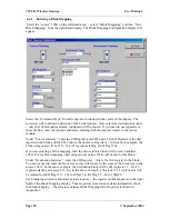
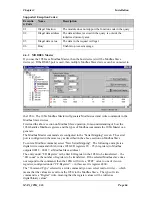
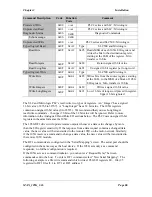
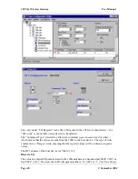
The reason for the offset is to stagger messages with the same time setting. For example, if
you configure 5 block mappings all to be sent at 10 minutes, then the 105G will try to send
these messages at the same time - some of the messages will have to wait until the earlier
messages have been sent. If you are sending Read messages as well as Write messages, then
the return messages could clash with outgoing messages.
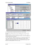
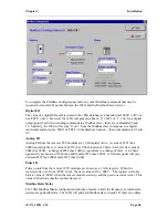
To avoid this, you can delay some messages using the Offset feature. For example, if you
have 5 mappings to be sent at 10 minutes, then the first could have zero offset, the second 3
sec offset, the third 6 sec offset etc.
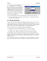
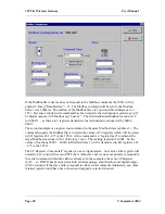
If you do not wish to have a real-time trigger, set “Period” to continuous.
If you want the block mapping to be sent only on real-time (and not on change as well),
select the “Disable” box in the bottom left hand corner - this disables change messages for
this block mapping.
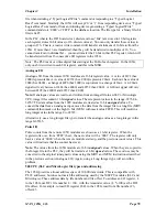
Setting the Clock
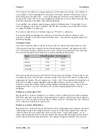
The clock within the 105G can be set by the host device, and read by the host device. The
105G provides four clock registers for days/hours/minutes/seconds - the registers are 4330 –
4333. On power-up, these registers are set to zero. Reg 4333 increments each second, Reg
4332 increments each minute, Reg 4331 each hour and Reg 4330 each day.
Item
Clock Location
Set Location
Days
4330
4340
Hours
4331
4341
Minutes
4332
4342
Seconds
4333
4343
The clock registers are used by the 105G for the real-time-clock trigger. The host device can
read these registers. The host device can also set the 105G clock at any time by writing to the
appropriate
Set
register. The
Set
registers are : 4340 – 4343. The procedure for setting the real
time clock via these registers depends on the module firmware version (to find out what
firmware version the module contains, simply display the diagnostics menu – see section on
diagnostics). The
set registers
can also be set via radio using appropriate I/O or block
mappings.
Firmware versions up to 1.50:
Registers 4340 – 4343 are normally zero. When a value is written into one of these registers,
the 105G copies the value into the corresponding clock register, and then sets the
Set
register
back to zero. For example, if the host device writes a value of 7 into Reg 4341, the 105G will
write 7 into 4331 and set 4341 back to zero.
Firmware version 1.50 and later:
Registers 4340 – 4343 will only be transferred to the corresponding clock registers when their
value changes from 0. For example to write a value of 7 to the hours register, first write the
value 0 to the
Set hours
register 4341, then write the value 7 to the same register. (i.e. by
always first writing the value 0 to the
Set
register this ensures that the change-of-state from 0
will be detected). Values must be held (i.e. not change) for approx 200msec to be detected.

