


Chapter 3
Installation
MAN_105G_1.16
Page 116
Conversely, for Modbus bit/binary commands the appropriate 0x or 1x prefix may need to be
added depending on the host device. The example below shows 8 bits being read from
Modbus locations 16385 – 16392 into I/O registers 4300 – 4307 (DOT 1-8). The
Modbus/TCP host device would write to these as Modbus addresses 016385 – 016392 (using
the 0x prefix to denote output coils).
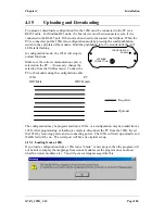
C
onnect Timeout
The Connect Timeout parameter in the Modbus TCP section of the display refers to the
Modbus TCP functionality of the module. If a TCP connection to the module has not been
active for this amount of time, the 105G will timeout and disconnect that connection. Note
that there can be several active connections at the same time - only the inactive connection
will be disconnected.
4.11.3
EtherNet/IP
Ethernet/IP (Ethernet Industrial Protocol) is based on the Control and Information Protocol
(CIP), which is also the framework for both DeviceNet and ControlNet, to carry and
exchange data between nodes. The Ethernet/IP implementation is a Level 2 I/O Server, which
means that the module will respond to both explicit and IO messages but requires that an
Ethernet/IP client initiate IO connections.
For additional information on the Ethernet/IP protocol see www.ethernet-ip.org and
www.odva.org. The rest of this section assumes the reader is familiar with Ethernet/IP.
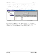
If you use the 105U-G with a PLC, the PLC configuration tool will require an EDS file so it
can recognise the Ethernet/IP interface in the 105U-G. The file is available on the same CD
as the configuration software, or on the ELPRO web site.
Implemented Objects
EtherNet/IP requires some mandatory objects; these are implemented, as well as some vendor
specific objects. The mandatory objects are the ones in the specification from ODVA.
The following vendor specific objects are implemented:
• I/O data input mapping object, Class A0h
• I/O data output mapping object, Class A1h
The 105G can handle multiple EtherNet/IP connections simultaneously - up to 6 produced
IO connections (“write” connections) and 6 consumed IO connections (“read” connections).
Each connection is a “virtual” connection, not a “physical” connection and is called an “I/O
instance”.
The maximum individual connection size is 512 bytes. If more than 512 bytes is to be
transferred, then more than one connection is required - a connection is known as an “IO
Instance”. Ethernet/IP interface to these IO connections is made available in the mandatory
Ethernet/IP ‘Assembly Object’ (class 04h) as vendor specific instance attributes 64h-69h for
produced IO (i.e. IO data configured using fieldbus
write
commands) and 96-9Bh for
consumed IO (i.e. IO data configured using fieldbus
read
commands). The same IO are also
available in the vendor specific objects I/O data input mapping object (class A0h) and IO data
output mapping object (class A1h) respectively as instance attributes 1 – 6. (See Object
Specifications below)
To make I/O data available via Ethernet/IP, ensure that the Enable Ethernet/IP checkbox on
the Ethernet Settings page is checked. Appropriate Fieldbus Mappings need to be configured
to link the required I/O registers to the Fieldbus Interface, as described above in the Profibus
and Modbus/TCP sections. An “
I/O Instance”
for each fieldbus link must also be specified


