


Chapter 3
Installation
MAN_105G_1.16
Page 124
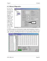
The fieldbus write mapping, seen above, links the 48 I/O registers 0 – 47 to the fieldbus
interface 4X registers 40001 – 40048. As described earlier, fieldbus interface registers 40001
– 40032 are always assigned as Global Data Out registers (i.e. Data To Network), these
registers will be broadcast to the network on each token rotation cycle. The remaining
registers (40033 – 40048) can be accessed via Modbus 40000 point-to-point Read Register
commands described in section 4.10.4. NOTE - the option also exists for the Global Data
output registers 40001 – 40032 to be read by the point-to-point commands also.
The fieldbus read mapping, seen above, links the 48 fieldbus interface registers 41025 –
41072 to the I/O registers 50 – 97. As described earlier, fieldbus interface registers 41025 –
41056 are always assigned as Global Data In registers (i.e. Data From Network). These
registers will be filled with Global Data broadcast by the “Source Unit” according to the
“GDB I/P Offset” and “GDB I/P Count” parameters. In the above example, the values of the
Offset = 0 and Count = 32, indicating that the entire 32 word Global Data broadcast from the
Source Unit will be read into fieldbus interface registers 41025 – 41056. Other nodes on the
network can write to the remaining registers (41057 – 41072) only by using the Modbus
point-to-point Write Register commands described in section 4.10.3. NOTE – the point-to-
point Write Register commands can
not
be used to write to the Global Data Input registers
41025 – 41056.
Finally, it must be taken into consideration that the 105G Modbus Plus module dynamically
adjusts the 4X register range available to the network depending on the fieldbus mappings
configured. The 105G will terminate the available 4X register range at the last mapped 4X
register for both the read and write area. In the example above this means that the only 4X
registers that are available to the Modbus Plus network are 40001 – 40048 and 41025 –
41072.
NOTE – considering this constraint, it is still strongly advised to use fieldbus interface
registers always starting at the lowest addressed locations, thus limiting unnecessary
processing overhead on the 105G.


