

Chapter 3
Installation
MAN_105G_1.16
Page 32
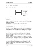
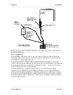
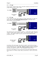
3.3.1
AC Supply
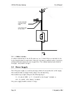
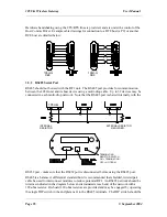
The AC supply is connected to the “SUP1” and “SUP2” terminals as shown below. The AC
supply should be “floating” relative to earth.
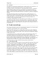
3.3.2
DC Supply
For DC supplies, the positive lead is connected to “SUP1” and the negative to “GND”. The
positive side of the supply
must not be connected to earth.
The DC supply may be a
floating supply or negatively grounded.
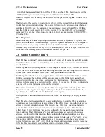
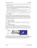
The module may also be powered from an external 11 – 15 VDC battery supply without the
need for a “normal” supply connected to “SUP1”. This external battery supply is connected
to “BAT+” and “GND” terminals. The positive lead of the external supply should be
protected by a 5A fuse.
Upon failure of the normal supply, the module may continue to operate for several hours
from a backup battery. The battery charger is designed for sealed or vented lead acid batteries
between 5 and 24 amphours -
other types of batteries should not be used
. Typically, a 5
Ahr battery will supply the 105G for 1 – 2 days, depending on the type of 105G.
On return of normal supply, the unit will recharge the battery. The maximum output of the
battery charger is 0.7A when the supply voltage is greater than 12V, and 0.3A for less than
12V.
SUP1
SUP2
GND
BAT+
12 – 24 VAC
Power
Supply
AC Out
-
+
105U-G
Optional Battery
Fuse 5A
GND
SUP1
SUP2
GND
BAT+
9 – 30 VDC
Power
Supply
DC Out
-
+
105U-G
Optional Battery
Fuse 5A
+
SUP1
SUP2
GND
BAT+
-
+
105U-G
BATTERY SUPPLY
11-15 VDC
Fuse 5A


