5.3
Installation and operation
compressor. If you are unsure of the weight, then weigh
the compressor before lifting it.
Make sure the lifting hook has a functional safety latch,
or equivalent, and is fully engaged and latched on the
bail.
Use guide ropes or equivalent to prevent twisting or
swinging of the machine once it has been lifted clear off
the ground.
Do not attempt to lift the compressor in high winds.
Keep all personnel away from the compressor when it is
suspended.
Do not lift the compressor higher than necessary.
Make sure the lift operator is present throughout the
duration that the compressor is suspended.
Set the compressor down only on a level surface that is
capable of supporting at least its net weight plus an
additional 10 per cent allowance .
5.1.4 Site requirements
Install the air compressor in a clean, dry, cool, and dust
free room as extreme temperatures (hot or cold),
moisture, and airborne contaminants can significantly
affect compressor performance, durability, and
compressed air quality.
Be aware the entrance to the compressor room should
be high enough and wide enough to carry the
compressor in and out.
Leave a minimum of 1m (3.28ft) space around the
compressor for safe and proper inspection, cleaning,
and maintenance activities.
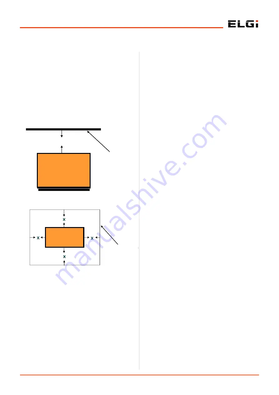
Leave a minimum of 2m (6.56ft) space above the
compressor for hot air to flow away from the
compressor.
Ensure the compressor is protected against direct
sunlight and rain.
Avoid exposing the compressor to excessive moisture
(from rain, dryer vent, etc.) as moisture can affect
airend lubrication, promote rust formation on the
compressor, and lead to electrical problems of the
motor.
Neither install the machine in a location where flame is
used nor place any inflammable objects near the
compressor.
Ensure the room temperature is within 45
o
C (113
o
F), as
high ambient temperatures will result in reduced oil life
due to higher discharge oil temperature (DOT). It also
results in high approach temperatures affecting the
cooling and condensation efficiency in the after-cooler
and in air treatment equipment like air dryers.
Ensure the hot medium of other utility equipment like
gensets/dryers/ boilers, etc., is not sucked by the
compressor inlet or that in any way the room
temperature does not rise to prevent high discharge oil
temperature.
Ensure the ambient temperature does not drop below
0
o
C (32
o
F). Provide air supply openings and adjustable
louvers to ensure that the minimum temperature does
not drop down below 0
o
C (32
o
F).
Install the compressor on a smooth, solid, level
industrial concrete floor capable of bearing the weight of
the compressor. Ensure unevenness of the surface is
within 6mm (0.25") and taper is within 50 per meter.
If the floor is splashed frequently with water while
cleaning, then place your compressor on a raised
concrete plinth 100 to 150 mm (4 to 6 inches) high.
Ensure the compressor base makes 100% contact
directly with the floor.
Know that an industrial floor with a level surface
capable of supporting the weight of the compressor is
sufficient for installing your compressor. No special
foundation or anchoring is necessary for rotary screw
compressors.
Do not store toxic, volatile, or corrosive agents near the
compressor.
Isolate the compressor from corrosive agents like
ammonia, chlorine, salt spray, and other chemicals as
Figure 3. Vertical clearance around the
compressor
MINIMUM 2 m (6.6 ft) CLEARANCE
CEILING
ELGi SCREW AIR
COMPRESSOR
Figure 4. Horizontal clearance around the
compressor
ELGi SCREW AIR
COMPRESSOR
MINIMUM CLEARANCE, X=1 m (3.5 ft)
WALLS OR
OTHER
EQUIPMENTS
Содержание EN 30X-100
Страница 1: ......
Страница 2: ......
Страница 3: ...Product Manual EN Series Electric Powered Screw Air Compressor EN 37 100 208 230 460V 3Ph 60Hz...
Страница 8: ......
Страница 19: ......
Страница 20: ......
Страница 21: ......
Страница 59: ...Controller Manual Neuron XT Version 3 0 January 2018...
Страница 80: ...7 22 Controller Manual Menu Structure...
Страница 81: ...PARTS MANUAL EN SERIES ELECTRIC POWERED SCREW AIR COMPRESSOR EN 30X EN 37...
Страница 82: ...8 2 Parts Manual 8 0 Air inlet and control system Ref 015315272 X016550 21...
Страница 84: ...9 1 Parts Manual 9 0 Drive system Ref 015310622 X015310 EN 37 100 PSI...
Страница 86: ...10 1 Parts Manual 10 0 Discharge system Ref 015310612 X015300 EN 30 EN 37...
Страница 88: ...11 1 Parts Manual 11 0 Cooling system Ref 015310616 X015304 EN 37...
Страница 90: ...12 1 Parts Manual 12 0 Lubrication system Ref 015315274 X016552 EN 37...
Страница 92: ...13 1 Parts Manual 13 0 Base and canopy system Ref 015310618 X015306 EN 37...
Страница 96: ...12 3 Kit Details...
Страница 97: ...POWER CIRCUIT 8 3 1 0 6 2 2 2 9...
Страница 98: ...CONTROL CIRCUIT 6 2 1 8 0 3 2 2 9...
Страница 99: ...BOM 8 1 0 3 6 2 2 2 9...
Страница 100: ...PANEL LAYOUT 0 2 6 3 1 8 2 2 9...
Страница 101: ...POWER CIRCUIT 8 3 1 0 6 2 2 2 9...
Страница 102: ...CONTROL CIRCUIT 6 2 1 8 0 3 2 2 9...
Страница 103: ...BOM 8 1 0 3 6 2 2 2 9...
Страница 104: ...PANEL LAYOUT 0 2 6 3 1 8 2 2 9...
Страница 107: ......
Страница 108: ......


